NCP1251
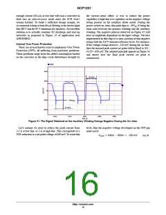
Latching Off the Controller
In our flyback design, let’s assume that our primary
inductance L is 770 mH, and the SMPS delivers 19 V with
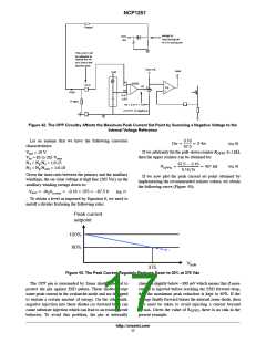
The OPP pin not only allows a reduction of the peak
current set point in relationship to the line voltage, it also
offers a means to permanently latch−off the part. When the
p
a N :N ratio of 1:0.25. The off−time primary current slope
p
s
S is thus given by:
p
part is latched−off, the V pin is internally pulled down to
ǒV ) V ǓN
CC
p
s
around 7 V and the part stays in this state until the user cycles
out
f
N
(
)
19 ) 0.8 4
Sp +
+
+ 103 kAńs
the V
down and up again, e.g. by un−plugging the
CC
770m
Lp
(eq. 11)
converter from the mains outlet. It is important to note that
the SCR maintains its latched state as long as the injected
current stays above the minimum value of 30 mA. As the
SCR delatches for an injected current below this value, it is
the designer duty to make sure the injected current is high
enough at the lowest input voltage. Failure to maintain a
sufficiently high current would make the device auto
recover. A good design practice is to ensure at least 60 mA
at the lowest input voltage. The latch detection is made by
observing the OPP pin by a comparator featuring a 3 V
reference voltage. However, for noise reasons and in
particular to avoid the leakage inductance contribution at
turn off, a 1 ms blanking delay is introduced before the
output of the OVP comparator is checked. Then, the OVP
comparator output is validated only if its high−state duration
lasts a minimum of 600 ns. Below this value, the event is
ignored. Then, a counter ensures that 4 successive OVP
events have occurred before actually latching the part. There
are several possible implementations, depending on the
needed precision and the parameters you want to control.
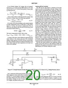
The first and easiest solution is the additional resistive
divider on top of the OPP one. This solution is simple and
inexpensive but requires the insertion of a diode to prevent
disturbing the OPP divider during the on time.
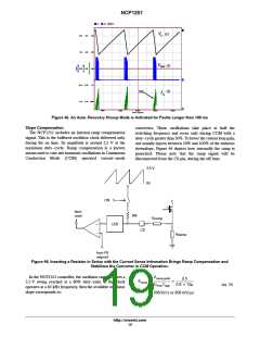
Given a sense resistor of 330 mW, the above current ramp
turns into a voltage ramp of the following amplitude:
Ssense + SpRsense + 103k 0.33
(eq. 12)
+ 34 kVńs or 34 mVńms
If we select 50% of the downslope as the required amount
of ramp compensation, then we shall inject a ramp whose
slope is 17 mV/ms. Our internal compensation being of
208 mV/ms, the divider ratio (divratio) between R
the internal 20 kW resistor is:
and
comp
17m
(eq. 13)
divratio +
+ 0.082
208m
The series compensation resistor value is thus:
Rcomp + Rramp @ divratio + 20k 0.082 [ 1.6 kW
(eq. 14)
A resistor of the above value will then be inserted from the
sense resistor to the current sense pin. We recommend
adding a small capacitor of 100 pF, from the current sense
pin to the controller ground for an improved immunity to the
noise. Please make sure both components are located very
close to the controller.
D2
1N4148
R3
5k
11
RoppU
421k
VCC
8
9
OP P
aux.
winding
4
5
10
ROPPL
1
1k
C1
100p
OVP
OPP
Vlatch
Figure 47. A Simple Resistive Divider Brings the OPP Pin Above 3 V in Case of a VCC Voltage Runaway above
18 V
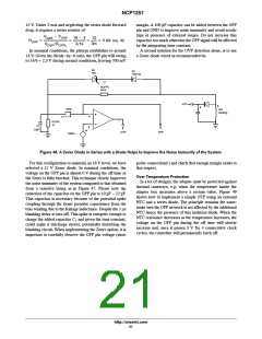
First, calculate the OPP network with the above equations.
Then, suppose we want to latch off our controller when V
0.18
0.25
(eq. 15)
Vaux,OVP + 25
+ 18 V
out
exceeds 25 V. On the auxiliary winding, the plateau reflects
the output voltage by the turns ratio between the power and
the auxiliary winding. In case of voltage runaway for our
19 V adapter, the plateau will go up to:
Since our OVP comparator trips at a 3 V level, across the
1 kW selected OPP pulldown resistor, it implies a 3 mA
current. From 3 V to go up to 18 V, we need an additional
http://onsemi.com
20

 ONSEMI [ ONSEMI ]