NCP1251
APPLICATION INFORMATION
Introduction
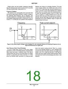
26 kHz (typical) reached for a feedback level of
roughly 350 mV. At this point, if the power continues to
drop, the controller enters classical skip−cycle mode.
The NCP1251 implements a standard current mode
architecture where the switch−off event is dictated by the
peak current setpoint. This component represents the ideal
candidate where low part−count and cost effectiveness are
the key parameters, particularly in low−cost ac−dc adapters,
open−frame power supplies etc. Capitalizing on the
NCP120X series success, the NCP1251 packs all the
necessary components normally needed in today modern
power supply designs, bringing several enhancements such
as a non−dissipative OPP.
• Internal soft−start: A soft−start precludes the main
power switch from being stressed upon start−up. In this
controller, the soft−start is internally fixed to 4 ms. The
soft−start is activated when a new startup sequence
occurs or during an auto−recovery hiccup.
• OVP input: The NCP1251 includes a latch input
(pin 3) that can be used to sense an overvoltage
condition on the adapter. If this pin is brought higher
• Current−mode operation with internal ramp
compensation: Implementing peak current mode
control at a fixed 65 kHz or 100 kHz, the NCP1251
offers an internal ramp compensation signal that can
easily by summed with the sensed current. Sub
harmonic oscillations are eliminated via the inclusion of
a single resistor in series with the current−sense
information.
than the internal reference voltage V
circuit permanently latches off. The V pin is pulled
down to a fixed level, keeping the controller latched.
The latch reset occurs when the user disconnects the
adapter from the mains and lets the V falls below the
, then the
CC
latch
CC
V
CC
reset.
• Latched OVP on V : It is sometimes interesting to
CC
implement a circuit protection by sensing the V
CC
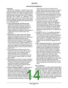
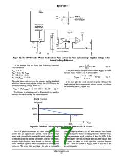
• Internal OPP: By routing a portion of the negative
voltage present during the on−time on the auxiliary
winding to the dedicated OPP pin (pin 3), the user has a
simple and non−dissipative means to alter the
maximum peak current setpoint as the bulk voltage
increases. If the pin is grounded, no OPP compensation
occurs. If the pin receives a negative voltage down to
–250 mV, then a peak current reduction down to 31.3%
typical can be achieved. For an improved performance,
the maximum voltage excursion on the sense resistor is
limited to 0.8 V.
• Low startup current: Achieving a low no−load
standby power always represents a difficult exercise
when the controller draws a significant amount of
current during start−up. Due to its proprietary
architecture, the NCP1251 is guaranteed to draw less
than 15 mA typical, easing the design of low standby
power adapters.
• EMI jittering: An internal low−frequency modulation
signal varies the pace at which the oscillator frequency
is modulated. This helps by spreading out energy in
conducted noise analysis. To improve the EMI
signature at low power levels, the jittering remains
active in frequency foldback mode.
• Frequency foldback capability: A continuous flow of
pulses is not compatible with no−load/light−load
standby power requirements. To excel in this domain,
the controller observes the feedback pin and when it
reaches a level of 1.5 V, the oscillator then starts to
reduce its switching frequency as the feedback level
continues to decrease. When the feedback pin reaches
1.05 V, the peak current setpoint is internally frozen and
the frequency continues to decrease. It can go down to
level. This is what the NCP1251 does by monitoring its
pin. When the voltage on this pin exceeds 25 V
typical, the pulses are immediately stopped and the part
latches off. The Vcc is maintained to 7 V typical and
remains in this state until the user unplugs the power
supply.
V
CC
• Short−circuit protection: Short−circuit and especially
over−load protections are difficult to implement for
transformers with high leakage inductance between
auxiliary and power windings (the aux winding level
does not properly collapse in presence of an output
short). Here, every time the internal 0.8 V maximum
peak current limit is activated (or less when OPP is
used), an error flag is asserted and a time period starts,
thanks to an internal timer. If the timer reaches
completion while the error flag is still present, the
controller stops the pulses and goes into a latch−off
phase, operating in a low−frequency burst−mode. When
the fault is cleared, the SMPS resumes operation.
Please note that some versions offer an auto−recovery
mode as described and some latch off in case of a short
circuit.
Start−up Sequence
The NCP1251 start−up voltage is made purposely high to
permit a large energy storage in a small V capacitor value.
CC
This helps to operate with a small start−up current which,
together with a small V capacitor, will not hamper the
CC
start−up time. To further reduce the standby power, the
start−up current of the controller is extremely low, below
15 mA maximum. The start−up resistor can therefore be
connected to the bulk capacitor or directly to the mains input
voltage to further reduce the power dissipation.
http://onsemi.com
14

 ONSEMI [ ONSEMI ]