NCP1251
R3
200k
3
10
R2
200k
5
D2
D1
1N4007
1N4007
11
1
12
R1
200k
Cbulk
22uF
D6
1N4148
D5
1N4935
input
mains
VCC
2
4
D4
1N4007
D3
1N4007
aux.
C1
4.7uF
C3
47uF
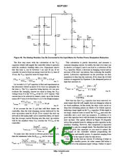
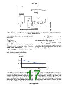
Figure 40. The Startup Resistor Can Be Connected to the Input Mains for Further Power Dissipation Reduction
The first step starts with the calculation of the V
capacitor which will supply the controller when it operates
until the auxiliary winding takes over. Experience shows
This calculation is purely theoretical, and assumes a
constant charging current. In reality, the take over time can
be shorter (or longer!) and it can lead to a reduction of the
CC
that this time t can be between 5 ms and 20 ms. If we
V
CC
capacitor. Hence, a decrease in charging current and an
1
consider we need at least an energy reservoir for a t time of
increase of the start−up resistor, thus reducing the standby
power. Laboratory experiments on the prototype are thus
mandatory to fine tune the converter. If we chose the 413 kW
resistor as suggested by Equation 4, the dissipated power at
high line amounts to:
1
10 ms, the V capacitor must be larger than:
CC
ICCt1
3m 10m
CVCC
w
w
w 3.3 mF
9
VCCon * VCCmin
(eq. 1)
Let us select a 4.7 mF capacitor at first and experiments in
the laboratory will let us know if we were too optimistic for
ǒ230 2Ǔ2
Ǹ
2
Vac,peak
PRstart*up
+
+
+
the time t . The V capacitor being known, we can now
1
CC
4Rstart*up
4 413k
(eq. 5)
evaluate the charging current we need to bring the V
CC
voltage from 0 to the VCC of the IC, 18 V typical. This
on
2302
+ 64 mW
current has to be selected to ensure a start−up at the lowest
mains (85 V rms) to be less than 3 s (2.5 s for design margin):
0.827Meg
Now that the first V capacitor has been selected, we
CC
VCConC
18 4.7m
VCC w
w 34 mA
must ensure that the self−supply does not disappear when in
no−load conditions. In this mode, the skip−cycle can be so
deep that refreshing pulses are likely to be widely spaced,
inducing a large ripple on the V capacitor. If this ripple is
too large, chances exist to touch the VCC
controller into a new start−up sequence. A solution is to
grow this capacitor but it will obviously be detrimental to the
start−up time. The option offered in Figure 40 elegantly
solves this potential issue by adding an extra capacitor on the
auxiliary winding. However, this component is separated
Icharge
w
2.5
2.5
(eq. 2)
If we account for the 15 mA that will flow inside the
controller, then the total charging current delivered by the
start−up resistor must be 49 mA. If we connect the start−up
network to the mains (half−wave connection then), we know
that the average current flowing into this start−up resistor
CC
and reset the
min
will be the smallest when V reaches the VCC of the
CC
on
controller:
Ǹ
V
2 * VCCon
ac,rms
p
from the V pin via a simple diode. You therefore have the
CC
(eq. 3)
ICVCC,min
+
ability to grow this capacitor as you need to ensure the
self−supply of the controller without jeopardizing the
start−up time and standby power. A capacitor ranging from
22 to 47 mF is the typical value for this device.
One note on the start-up current. If reducing it helps to
improve the standby power, its value cannot fall below a
certain level at the minimum input voltage. Failure to inject
Rstart*up
To make sure this current is always greater than 49 mA,
then the minimum value for R
can be extracted:
start−up
Ǹ
V
2 * VCCon
85 1.414 * 18
ac,rms
p
p
Rstart*up
v
v
v 413.5 kW
49m
ICVCC,min
(eq. 4)
http://onsemi.com
15

 ONSEMI [ ONSEMI ]