NCP1239
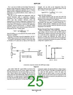
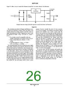
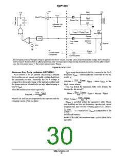
Figure 45 offers a way to connect the elements around Pin 5 to create a Brown−Out detection:
to converter
PFC
Preconverter
Rupper
Input
Filtering
Capacitor
AC line
+
5
Cbulk
Rlower
Cfil
Example where the voltage of the bulk capacitor is used for the brown−out Protection
Figure 45.
The calculation procedure for Rupper and Rlower is easy.
The first level transition is always clean: the SMPS is not
working during the startup sequence and there exists no
ripple superimposed on Cbulk. Supposed we want to start
the operation at Vbulk = Vtrip = 120 VDC (i.e., VinAC =
85 V).
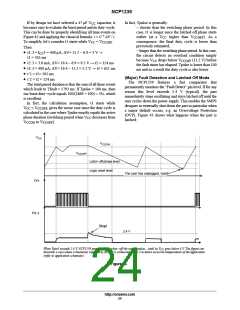
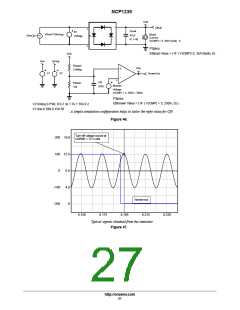
amount of power, actually the power of your converter
(35 W in our example). The equation associated to Bload
instructs the simulator not to draw current until the
Brown−Out converter gives the order, just like what the real
converter will do. As a result, Vbulk is free of ripple until the
node CMP goes high, giving the green light to switch pulses.
The input line is modulated by the “timing” node which
ramps up and down to simulate a slow startup/turn−off
sequence. Then, by adjusting the Cfil value, it becomes
possible to select the right turn−off AC voltage. Figure 47
portrays the typical signal you can expect from the
simulator. We measured a turn−on voltage of 85 VAC
whereas the turn−off voltage is 72 VAC. Further increasing
Cfil lowers this level (for instance, a 1 ꢁ F capacitor gives
VBO = 65 VAC in the example).
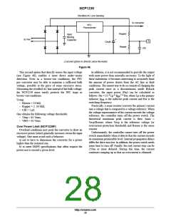
As we have seen, the load variations will modify this
turn−off level. To remove the dependency between VBO
and the load, it is possible to directly sense the rectified input
line present at the PFC stage input, as shown in Figure 48.
In that case, there still exists the input line ripple, but this
ripple is independent of the load. By adjusting Cfil
capacitance and the divider section, you can build a
brown−out detection independent of the load.
1. Fix a bridge current Ib compatible with your
standby requirements, for instance an Ib of 50 ꢁ A.
2. Then evaluate Rlower by: Rlower = 0.5/Ib =
10 kꢂ
3. Calculate Rupper by: (Vtrip – 0.5 V)/Ib =
(120 – 0.5)/50 ꢁ A = 2.39 Mꢂ
The second threshold, the level at which the power supply
stops (VBO), depends on the capacitor Cfil but also on the
selected bulk capacitor. Furthermore, when the load varies,
the ripple also does and increases as Vin drops. If Cfil allows
a too high ripple, chances exist to prematurely stop the
converter. By increasing Cfil, you have the ability to select
the amount of hysteresis you want to apply. The less ripple
appears on a Pin 5, the larger the gap between Vtrip and VBO
(the maximum being VBO = Vtrip/2). The best way to assess
the right value of Cfil, is to use a simple simulation sketch
as the one depicted by Figure 46. A behavioral source loads
the rectified DC line and adjusts itself to draw a given
http://onsemi.com
26

 ONSEMI [ ONSEMI ]