NCP1239
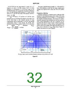
Rectified AC Line Sensing
to converter
PFC
Preconverter
Rupper
Rlower
Input
filtering
Capacitor
ac line
+
5
Cbulk
Cfil
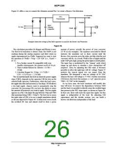
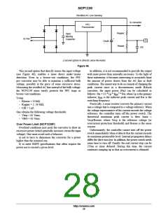
A second option to directly sense the mains
Figure 48.
This second option that directly senses the input voltage
(see Figure 48), enables a more direct under−mains
detection. Even in a brown−out conditions, the PFC
pre−converter may be able to maintain a sufficient bulk
voltage, possibly at the price of some excessive stress.
Measuring the rectified AC line instead of the bulk voltage,
the NCP1239 more surely protects the PFC stage in
brown−out conditions.
In addition, it is not recommended to provide the output
with more power than normally necessary. To the light of
these statements, it becomes interesting to accurately limit
the amount of power drawn from the AC line in fault
conditions. The easiest way to do so consists of clamping the
peak current since in a discontinuous mode flyback
converter, the input power (Pin) can be calculated as
2
follows: Pin = 1/2 * Lp * Ip * fsw, where Lp is the primary
pk
inductor, Ip is the inductor peak current and fsw is the
switching frequency.
pk
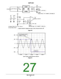
Using:
− Rlower = 10 kꢂ,
− Rupper = 2. 39 Mꢂ,
− Cfil = 1 ꢁ F,
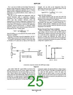
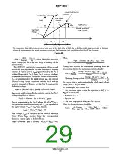
Practically, a sense resistor converts the primary current
into a voltage that is compared to a voltage reference. When
the voltage representative of the current exceeds the voltage
reference, the controller turns off the power switch. The
theoretical maximum peak current is then: Imax =
Vocp/Rsense, where Vocp is the reference voltage (or
overcurrent protection threshold) and Rsense is the sense
resistor.
Unfortunately, the controller cannot turn off the power
switch immediately when it detects that the current exceeds
its maximum permissible level. Internal propagation delays
differ the drive turn low. In addition, the power switch needs
some time to turn off. Finally, the real current stop can be
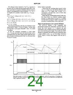
250ns or more delayed. During this time, the current
continues ramping up so that an overcurrent is obtained.
One obtains the following voltage thresholds:
− Vtrip = 85 Vrms,
− VBO = 65 Vrms.
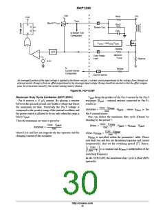
Over Power Limit (NCP1239F)
Overload conditions may push the converter to draw an
excessive power (which generally increases versus the input
voltage). One must avoid such a behavior:
a) not to have to dimension the converter for a power
higher than the nominal one,
b) to meet SMPS specifications that often request the
power not to exceed a given level.
http://onsemi.com
28

 ONSEMI [ ONSEMI ]