NCP1239
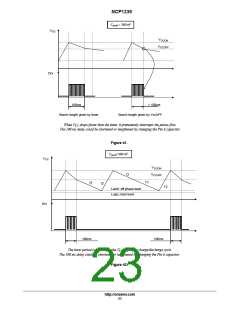
If by design we have selected a 47 ꢁ F V capacitor, it
becomes easy to evaluate the burst period and its duty−cycle.
This can be done by properly identifying all time events on
Figure 42 and applying the classical formula: t = C * DV / i.
In fact, Tpulse is generally:
− shorter than the switching phase period. In this
case, t1 is longer since the latched off phase starts
earlier (at a V higher than V ). As a
CC
CC
CCOFF
consequence, the final duty cycle is lower than
previously estimated,
− longer than the switching phase period. In this case,
the circuit detects an overload condition simply
To simplify, let’s consider t1 starts while V = V
.
CC
CCOFF
Then:
• t1: I = I 3 = 400 ꢁ A, ꢃV= 11.2 – 6.9 = 3 V ꢀ
CC
t1 = 505 ms
because V drops below V
(11.2 V) before
CC
CCOFF
• t2: I = 3.6 mA, ꢃV= 16.4 – 6.9 = 9.5 V ꢀ t2 = 124 ms
• t3: I = 400 ꢁ A, ꢃV= 16.4 – 11.2 = 5.2 V ꢀ t3 = 611 ms
• t’1 = t1= 505 ms
the fault timer has elapsed. Tpulse is lower than 100
ms and as a result the duty cycle is also lower.
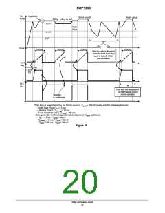
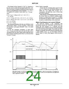
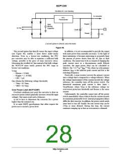
(Major) Fault Detection and Latched Off Mode
• t’2 = t2 = 124 ms
The NCP1239 features
a fast comparator that
The total period duration is thus the sum of all these events
which leads to Tfault = 1793 ms. If Tpulse = 100 ms, then
our burst duty−cycle equals 100/(1869 + 100) ≈ 5%, which
is excellent.
permanently monitors the “Fault Detect” pin level. If for any
reason this level exceeds 2.4 V (typical), the part
immediately stops oscillating and stays latched off until the
user cycles down the power supply. This enables the SMPS
designer to externally shut down the part in particular when
a major default occurs, e.g. an Overvoltage Protection
(OVP). Figure 43 shows what happens when the part is
latched:
In fact, the calculation assumption, t1 starts while
V
CC
= V , gives the worse case since the duty cycle is
CCOFF
calculated in the case where Tpulse exactly equals the active
phase duration (switching period when V decreases from
CC
V
CCON
to V
).
CCOFF
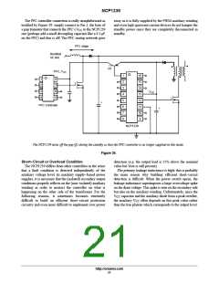
V
CC
V
CCON
V
CCOFF
Latch−off phase level
Logic reset level
The user has unplugged, reset!
Drv
Pin 3
Stop!
2.4 V
When Vpin3 exceeds 2.4 V, NCP1239 permanently latches−off the output pulses0until its V goes below 4 V. The figure can
CC
illustrate a case where a thermistor supplied by REF5V is connected to Pin 3 to detect excessive temperatures of the application
(refer to application schematic).
Figure 43.
http://onsemi.com
24

 ONSEMI [ ONSEMI ]