NCP1239
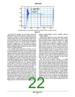
Leakage effect:
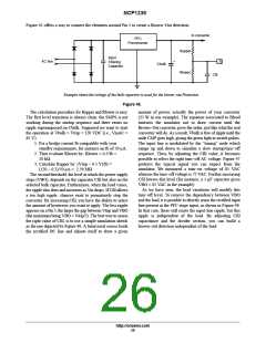
Vpeak = 24.2V
25.0
15.0
5.00
”clean” plateau
V = 13.4V
0V
−
5.00
−
15.0
236U
240U
244U
248U
252U
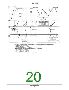
The leakage effect seen on the auxiliary side pulls−up the final level peak−rectified by the diode
Figure 40.
On Figure 40’s example, one can clearly observe the
elapsed, nothing happens and the controller continues
difference between the peak and the real plateau DC level.
The delta is around 10 V, which obviously degrades the
auxiliary image of the secondary side. When a short−circuit
occurs, the leakage can be so strong that the whole plateau
has dropped to a few volts, but the leakage contribution
becomes so energetic (Ip = Ip max.) that even a few ꢁ s
working normally.
When a fault is detected, we have seen that the controller
stops delivering pulses. At this time, V starts to drop
because the power supply is locked off. When the V drops
CC
CC
below V
(11.2 V typical), it enters a so−called
CCOFF
latch−off phase where the internal consumption is reduced
down to about 400 ꢁ A. The V capacitor continues to
duration is enough to prevent V auxiliary from collapsing
CC
CC
and thus stopping the pulses. Needless to say that over power
detection is simply impossible.
deplete, but at a lower rate. When V finally reaches the
latch−off level (around 6.9 V), the startup current source
CC
Low standby power requirement decreases V
at
turns on and pulls V above V
, exactly as a startup
CCON
CC
CC
no−load:this is particularly true if you try to reach less than
100 mW at high line. Due to skip−cycle, the continuous flow
of pulses turns into bunches of pulses (sometimes 1−2 pulses
only) that can be spaced by 50ms or more in certain cases.
The energy content in each bunch of pulses does not suffer
any attenuation. For instance, to lower Figure 40’s peak, you
could think of inserting a resistor with the auxiliary diode to
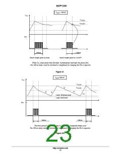
sequence would do. When V exceeds V
pulses are delivered and can last 100 ms maximum if there
is enough voltage or can be prematurely interrupted if V
(16.4 V),
CC
CCON
CC
falls below V . Figure 41 shows the difference between
CCOFF
these two cases. As already explained, in short−circuit
bursts, the PFC section is not validated.
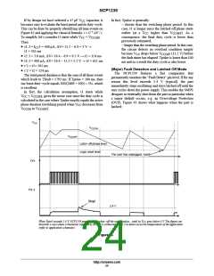
The short−circuit protection features a so−called
auto−recovery circuitry. That is to say, during the 100 ms
period, the power supply attempts to startup. If the fault has
gone, then the controller resumes from the fault and the
power supply operates again. If the fault is still present, the
pulses are stopped at the end of the 100 ms section (Tpulse)
for a given time period Tfault. At the end of Tfault, a new
100 ms attempt is made and so on. To avoid any thermal
runaway, a burst duty−cycle defined by Tpulse/(Tfault+
Tpulse) below 10% is desirable ((Tfault+Tpulse) is the burst
period). If the 100 ms is made by an internal timer in
conjunction with the Pin 6 capacitor, the Tfault duration
form a low pass filter with the V capacitor. Unfortunately,
CC
it would drastically reduce the V
capacitor refueling
CC
current and V could not be maintained. To compensate
CC
that effect, a solution could be to increase the turn ratio, but
then the peak rectification problem comes back again.
As one can see, a short−circuit protection free of the V
CC
level would be the best solution. This is exactly what the
NCP1239 delivers with the internal 100 ms timer (390 nF
being connected to Pin 6). As soon as the internal 0.9 V error
flag is asserted high, a 100 ms timer gets started. If the error
flag keeps asserted during the 100 ms period, then the
controller detects a true fault condition and stops pulsing the
output. If this is a simple transient overload, e.g. the error
flag goes back to a normal level before the 100 ms period has
builds on the V capacitor which is charged/discharged
CC
two times. Figure 42 on the following page portrays this
behavior.
http://onsemi.com
22

 ONSEMI [ ONSEMI ]