NCP1239
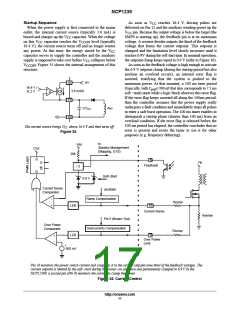
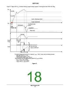
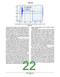
Figure 37 depicts the V evolution during a proper startup sequence, showing the state of the error flag:
CC
Vcc
VccON
VccOFF
Latch−off phase level
Logic reset level
FB
Feedback loop
reacts...
Full power
User
Powers up!
regulation
Skip level
Ip max
Error
Flag
7.5ms*
SS
No error has
been confirmed
Timer
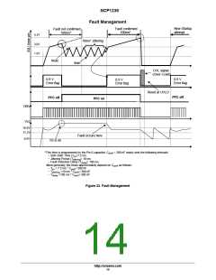
*This time is programmed by the Pin 6 capacitor. C
= 390 nF nearly sets the following intervals:
pin6
− Soft−Start Time (T ):7.5 ms
ss
jittering
− Jittering Period (T
): 10 ms
− Fault Detection Delay (T
): 100 ms
delay
More generally, the times approximately depend on C
as follows:
pin6
− T = 7.5 ms * C
/ 390 nF
ss
pin6
− T
− T
=10 ms * C
=100 ms * C
/ 390 nF
jittering
pin6
pin6
/ 390 nF
delay
Figure 37.
http://onsemi.com
18

 ONSEMI [ ONSEMI ]