NCP1239
PFC Startup Sequence
internal 0.9 V Zener diode actively clamping the current
amplitude to (0.9 V/Rsense). During this time, the NCP1239
asserts an error flag. A maximum current condition being
observed, the circuit determines if this state results from
either a normal response (startup or a transient period) or a
fault condition. To make the difference, each time the error
flag is asserted, a 100 ms timer starts to count down. If the
error flag keeps asserted for the 100 ms period, there is a
fault and the PWM controller enters a safe, auto−recovery,
burst mode to limit the dissipated heat (see below for more
details). During the Power−on sequence, “pfcON” keeps
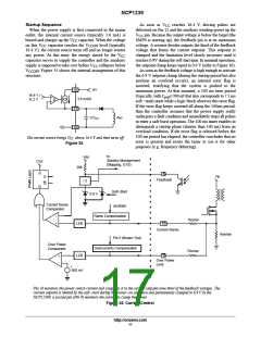
To ensure an adequate startup sequence of both PWM
section and the PFC stage, some logic and timing need to be
included as shown on the internal diagram. The key point
here is the fact that the PFC always starts after the PWM
section. As a result, the SMPS must be designed to cope with
transient universal mains operation. Why this? Because of
the light−to−heavy load transition where a case exists when
the PFC is off, the PWM in standby and the load is suddenly
applied. In this scenario, the PWM section must sustain the
entire transient period that lasts until the PFC re−starts since
it has been deactivated for standby.
low to pullup Pin 1 to V until the error flag is down. When
CC
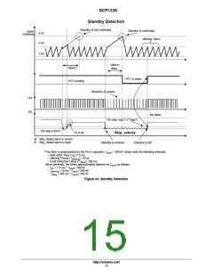
The standby detection block generates an internal signal
“pfcON” that controls Pin 1 in accordance to the operation
mode:
the error flag is down, the power supply has entered
regulation, its auxiliary voltage is stable, then Pin 1 can turn
low (1 mA sink current) to safely allow PFC operation.
Entering Standby: when skip−cycle starts to activate, a
100 ms countdown takes place and the logic observes the
skip activity. If the skip activity is still there at the end of the
100 ms, then standby is confirmed and the NCP1239 pulls
− “pfcON” is high in normal mode and a current source
draws 1 mA from Pin 1,
− “pfcON” is low in standby to disable the 1 mA current
source. A 10 kꢂ resistor pulls up Pin 1 to V
.
CC
up Pin 1 to V to shut down the PFC.
CC
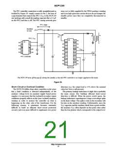
This configuration makes it ideal to drive a pnp transistor
Leaving standby: in this case, as soon as the skip−cycle
activity disappears, the circuit immediately re−activates the
1 mA sinking current source of Pin 1, to enable the PFC:
there is no reaction delay in this situation.
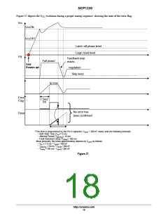
Short−circuitcondition: a short circuit is detected on the
primary side by measuring the time the error flag is asserted.
As explained, if this flag is asserted longer than 100 ms, then
the PWM stops oscillating and enters a safe burst mode. In
that connects or disconnects the NCP1239 V to the PFC
CC
controller one (refer to Figure 39). The “pfcON” signal is
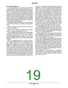
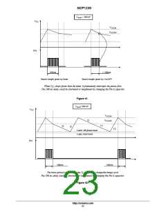
activated following Figure 38 diagram. Let’s split this
drawing in different time periods to clearly depict signal
assertions:
Power on: during this time, V
rises up, the V
CC
CC
capacitor being charged by the 3.6 mA current source. When
exceeds V (16.4 V typ.), driving pulses are
V
CC
CCON
this case, Pin 1 is pulled up to V and the PFC is shut down.
CC
delivered to the MOSFET in an attempt to crank the power
supply. V collapses (because the V capacitor alone
During the burst, it is not activated (PFC is off) until the fault
goes away and the power supply resumes operation. The
PFC being shut off in short−circuit conditions, it naturally
reduces the main MOSFET stress.
Latch−off mode: if the controller is permanently
latched−off due to a major fault (Pin 3 detection of an OVP
or an excessive external temperature), the PFC is kept off
CC
CC
delivers the energy) until sufficient auxiliary voltage is built
up in order to take over the startup sequence and thus
self−supply the controller. As long as the output voltage has
not reached its wished value, the controller pushes for the
maximum peak current. During the soft−start (7.5 ms with
390 nF on Pin 6), the maximum permissible current linearly
increases till the maximum peak setpoint is reached, the
(Pin 1 being tied to V ).
CC
http://onsemi.com
19

 ONSEMI [ ONSEMI ]