MT9M021, MT9M031
Digital
I/O
Digital
Core
PLL
Power
Analog
Analog
1
1
1
1
1
Power
Power
Power
Power
V
DD
_IO
V
DD
V
DD
_PLL
V
AA
V
AA
_PIX
Master Clock
(6−50 MHz)
D
[11:0]
OUT
EXTCLK
PIXCLK
To Controller
S
DATA
LINE_VALID
S
CLK
FRAME_VALID
From
Controller
TRIGGER
OE_BAR
STANDBY
FLASH
RESET_BAR
TEST
D
A
GND
GND
Digital
Ground
Analog
Ground
V
DD
_IO
V
DD
V
DD
_PLL
V
AA
V
AA
_PIX
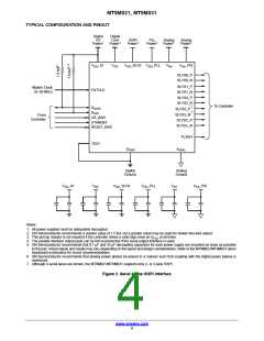
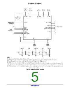
Notes:
1. All power supplies must be adequately decoupled.
2. ON Semiconductor recommends a resistor value of 1.5 kW, but a greater value may be used for slower two-wire speed.
3. This pull-up resistor is not required if the controller drives a valid logic level on S at all times.
CLK
4. The serial interface output pads can be left unconnected if the parallel output interface is used.
5. ON Semiconductor recommends that 0.1 mF and 10 mF decoupling capacitors for each power supply are mounted as close as possible
to the pad. Actual values and results may vary depending on the layout and design considerations. Refer to the MT9M021/MT9M031 demo
headboard schematics for circuit recommendations.
6. ON Semiconductor recommends that analog power planes be placed in a manner such that coupling with the digital power planes is
minimized.
Figure 3. Parallel Pixel Data Interface
www.onsemi.com
5

 ONSEMI [ ONSEMI ]