MC44603
established by the Error Amplifier output (Pin 13). Thus, the
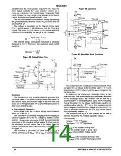
Figure 34. Oscillator
error signal controls the peak inductor current on a
cycle–by–cycle basis. The Current Sense Comparator PWM
Latch ensures that only a single pulse appears at the Source
Output during the appropriate oscillator cycle.
V
ref
0.4 I
ref
C
VOS prot
V
OSC prot
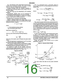
The inductor current is converted to a voltage by inserting
1.0 V
1.6 V
V
the ground referenced sense resistor R in series with the
OSC
S
C
power switch Q1.
OSC Low
R
Q
C
< 1.6 V
T
This voltage is monitored by the Current Sense Input
(Pin 7) and compared to a level derived from the Error Amp
output. The peak inductor current under normal operating
conditions is controlled by the voltage at Pin 13 where:
L
S
OSC
Discharge
R Q
C
OSC High
Synchro
10
Disch
S
C
T
3.6 V
V
Demag
Out
C
OSC Regul
V
(Pin 13) – 1.4 V
3 R
I
pk
0
1
S
The Current Sense Comparator threshold is internally
clamped to 1.0 V. Therefore, the maximum peak switch
current is:
1
0
I
Regul
I
Discharge
1.0 V
I
pk(max)
R
S
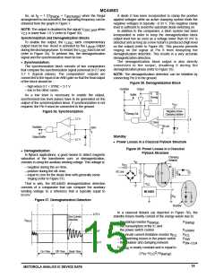
Figure 35. Simplified Block Oscillator
Figure 33. Output Totem Pole
V
ref
V
in
V
C
I
C
Charge
OSC Regul
14
0.4 I
ref
UVLO
1.6 V
V
10
OSC prot
R2
Q1
0
1
V
0: Discharge Phase
1: Charge Phase
Demag Out
3
C
S
R
R
T
R3
Thermal
Protection
Q
1N5819
I
Discharge
I
Regul
PWM
Latch
Current
Sense
Substrate
R
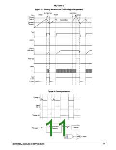
Two comparators are used to generate the sawtooth. They
compare the C voltage to the oscillator valley (1.6 V) and
Current Sense
Comparator
7
R
C
S
T
peak reference (3.6 V) values. A latch (L ) memorizes the
disch
oscillator state.
In addition to the charge and discharge cycles, a third
state can exist. This phase can be produced when, at the end
of the discharge phase, the oscillator has to wait for a
synchronization or demagnetization pulse before restarting.
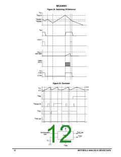
Oscillator
The oscillator is a very accurate sawtooth generator that
can work either in free mode or in synchronization mode. In
this second mode, the oscillator stops in the low state and
waits for a demagnetization or a synchronization pulse to
start a new charging cycle.
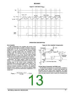
During this delay, the C voltage must remain equal to the
T
oscillator valley value ( 1.6 V). So, a third regulated current
sourceI
controlledbyC ,isconnectedtoC in
Regul
OSCRegul T
• The Sawtooth Generation:
In the steady state, the oscillator voltage varies between
about 1.6 V and 3.6 V.
order to perfectly compensate the (0.4 I ) current source
that permanently supplies C .
The maximum duty cycle is 80%. Indeed, the on–time is
allowed only during the oscillator capacitor charge.
ref
T
The sawtooth is obtained by charging and discharging an
external capacitor C (Pin 10), using two distinct current
T
Consequently:
sources = I
and I
. In fact, C is permanently
charge
discharge T
T
T
= C x ∆V/I
charge
T charge
connected to the charging current source (0.4 I ) and so,
the discharge current source has to be higher than the
ref
= C x ∆V/I
discharge
discharge
T
where:
charge current to be able to decrease the C voltage (refer
T
T
is the oscillator charge time
charge
∆V is the oscillator peak–to–peak value
is the oscillator charge current
to Figure 35).
This condition is performed, its value being (2.0 I ) in
ref
in standby mode).
I
charge
normal working and (0.4 I + 0.5 I
ref
F Stby
and
T
is the oscillator discharge time
is the oscillator discharge current
discharge
discharge
I
14
MOTOROLA ANALOG IC DEVICE DATA

 ONSEMI [ ONSEMI ]