MC44603
P
only depends on the current drawn from the mains.
The V
threshold level is typically equal to
ICL
CS
)/3] and if the corresponding power threshold is
Losses can be considered constant. This waste of energy
decreases when the standby losses are reduced.
[(V
R P Stby
labelled P
P
:
thL
P
increases when the oscillator frequency is
V
control
2
R P Stby
3.0 R
S
0.5 x L x
x f
S
thL
increased (each switching requires some energy to turn on
the power switch).
And as:
P
and P are proportional to the switching
SW
frequency.
SN–CLN
V
R
x 0.4 x I
x 0.4 x
ref
R P Stby
P Stby
Consequently, standby losses can be minimized by
decreasing the switching frequency as much as possible.
The MC44603 was designed to operate at a standby
frequency lower than the normal working one.
V
ref
ref
R
R P Stby
R
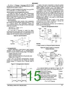
• Standby Power Calculations with MC44603
During a switching period, the energy drawn by the
transformer during the on–time to be transferred to the output
during the off–time, is equal to:
10.6 x R x R
P
S
ref
thL
L x f
R
x
P Stby
V
ref
Thus, when the power drawn by the converter decreases,
decreases and when V becomes lower than [V
S
V
CS
x (V
1
2
CS
CS–th
2
E
x L x I
pk
)/3], the standby mode is activated. This results in
R P Stby
an oscillator discharge current reduction in order to increase
the oscillator period and to diminish the switching frequency.
As it is represented in Figure 40, the (0.8 x I ) current
where:
– L is the transformer primary inductor,
– l is the inductor peak current.
pk
ref
source is disconnected and is replaced by a lower value one
(0.25 x I
).
F Stby
Input power is labelled P :
in
2
0.5 x L x I x f
pk
S
P
Where: I
= V /R
ref F Stby
in
F Stby
where f is the normal working switching frequency.
S
In order to prevent undesired mode switching when power
is close to the threshold value, a hysteresis that is
Also,
proportional to V
is incorporated creating a second
R P Stby
thresholdlevelthatisequalto[2.5x(V
V
R
CS
I
pk
V
)/3].When
CS
RPStby
S
the standby comparator output is high, a second current
where R is the resistor used to measure the power switch
S
source (0.6 x I ) is connected to Pin 12.
ref
current.
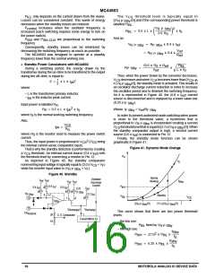
Finally, the standby mode function can be shown
graphically in Figure 41.
2
Thus, the input power is proportional to V
(V
being
CS
CS
the internal current sense comparator input).
That is why the standby detection is performed by creating
a V threshold. An internal current source (0.4 x I ) sets
the threshold level by connecting a resistor to Pin 12.
As depicted in Figure 40, the standby comparator
Figure 41. Dynamic Mode Change
CS
ref
P
in
f
S
noninverting input voltage is typically equal to (3.0 x V
+ V )
CS
F
while the inverter input value is (V
+ V ).
R P Stby
F
Figure 40. Standby
Normal
Working
Oscillator
Discharge
Current
V
V
ref ref
f
Stby
V
V
ref ref
0.6 I
1
P
thH
ref
0.4 I
0.8 I
ref
ref
V
0.25
I
ref
F Stby
R
0.2 I
P Stby
ref
0
Standby
P
thL
V
CS
12
1
0
C
Stby
[(V
R P Stby
)/3]
2.5 x [(V )/3]
R P Stby
1
13
I
I
Discharge
Discharge/2
This curve shows that there are two power threshold
levels:
ER
AmpOut
2R
1R
C. S. Comparator
Current Mirror X2
– the low one:
– the high one:
P
fixed by V
2
thL
R P Stby
f
Stby
P
(2.5) x P
x
f
thH
thL
f
S
Stby
P
6.25 x P
x
thH
thL
f
S
16
MOTOROLA ANALOG IC DEVICE DATA

 ONSEMI [ ONSEMI ]