AC Electrical Characteristics
All typical value are for VCC = 3.6V at 25ºC unless otherwise specified.
TA = - 40 to +85°C
Symbol
Parameter
VCC (V)
Conditions
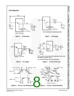
V/R,/L = 1.0V
Unit
Min. Typ.(6) Max.
RL = 50Ω, CL = 50Pf
Figure 9, Figure 10,
Figure 11
tON
Turn-On Time, /OE to Output
2.7 to 4.3
2
2
μs
V/R,/L = 1.0V
RL = 50Ω, CL = 50pF
Figure 9, Figure 10,
Figure 11
tOFF
Turn-Off Time, /OE to Output
2.7 to 4.3
μs
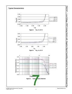
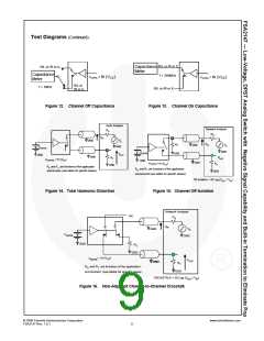
f = 20kHz, RT = 32Ω,
3.3 to 4.3 CL = 0pF
Figure 16
Non-Adjacent Channel Crosstalk
(Audio Mode)
Xtalk
THD
-75
0.05
80
dB
%
f = 20Hz to 20 kHz
3.0 to 4.3 RL = 32Ω, VIN = 2Vpp
Total Harmonic Distortion
(Audio Mode)
Figure 14
f = 20kHz to 20kHz,
3.3 to 4.3 RL = 32Ω, VIN = 2VPP
Figure 14
Signal-to-Noise Ratio (Audio
Mode)
SNR
dB
Note:
6. Guaranteed by characterization; not production tested.
Capacitance
All typical values are at 25ºC unless otherwise specified.
TA = - 40 to +85°C
Symbol
Parameter
VCC (V)
Conditions
Unit
Min. Typ.(7) Max.
CIN
Control Pin Input Capacitance
3.0 to 4.3 VBIAS = 0.2V
2.5
pF
Note:
7. Guaranteed by characterization; not production tested.
© 2008 Fairchild Semiconductor Corporation
www.fairchildsemi.com
FSA2147 Rev. 1.0.1
5

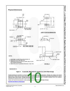
 ONSEMI [ ONSEMI ]