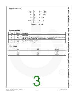
Pin Configuration
NC
/R
VCC
/OE
R
1
8
2
7
/L
3
4
6
5
GND
L
Figure 2.
8-Pin US8
Pin Descriptions
Pin #
Name
Description
Power supply.
8
VCC
Output enable. This pin defaults HIGH, allowing the user to mute the audio channel during
power up. The audio path is only connected when /OE is driven LOW.
7
/OE
6, 5
2, 3
R, L
Audio right and left input sources.
Audio common connector port.
/R, /L
Truth Table
VCC
/OE
Switch
LOW
HIGH
HIGH
OPEN
ON
LOW
HIGH
OPEN
© 2008 Fairchild Semiconductor Corporation
FSA2147 Rev. 1.0.1
www.fairchildsemi.com
2

 ONSEMI [ ONSEMI ]