MC44608
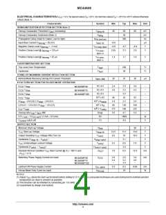
ELECTRICAL CHARACTERISTICS(V
noted) (Note 1)
=12V,fortypicalvaluesT =25°C,formin/maxvaluesT =–25°Cto+85°Cunlessotherwise
CC
A
A
Characteristic
Symbol
Min
Typ
Max
Unit
DEMAGNETIZATION DETECTION SECTION (Note 2)
Demag Comparator Threshold (V
increasing)
V
30
50
30
69
mV
mV
ns
A
pin1
dmg–th
Demag Comparator Hysteresis (Note 3)
H
dmg
Propagation Delay (Input to Output, Low to High)
t
300
PHL(In/Out)
Input Bias Current (V
= 50 mV)
I
–0.6
–0.9
2.05
demag
dem–lb
Negative Clamp Level (I
= –1 mA)
V
–0.7
2.3
–0.4
2.8
V
demag
cl–neg–dem
Positive Clamp Level @ I
= 125
A
V
V
demag
cl–pos–
dem–H
Positive Clamp Level @ I
= 25
A
V
1.4
1.7
1.9
V
demag
cl–pos–
dem–L
OVERTEMPERATURE SECTION
Trip Level Over Temperature
Hysteresis
T
T
160
30
°C
°C
high
hyst
STAND–BY MAXIMUM CURRENT REDUCTION SECTION
Normal Mode Recovery Demag Pin Current Threshold
K FACTORS SECTION FOR PULSED MODE OPERATION
I
20
25
30
A
dem–NM
I
I
I
I
/ I
10 x K1
10 x K1
10 x K1
2.4
2.8
2.9
3.3
3.8
4.2
–
–
–
–
–
–
–
–
CCS stup
MC44608P40
MC44608P75
MC44608P100
/ I
CCS stup
/ I
CCS stup
3.5
3
/ I
CCL stup
10 x K2
46
1.8
90
52
63
2.6
150
225
5.5
2
(V
stup
– UVLO2) / (V
stup
– UVLO1)
– UVLO1)
10 x K
sstup
2.2
2
(UVLO1 – UVLO2) / (V
stup
10 x K
120
198
4.7
sl
6
I
/ V
10 x Y
175
3.0
CS csth
cstby
Demag ratio I
/ I
ovp dem
NM
Dmgr
(V3
– V3 ) / (1 mA – 0.5 mA)
R3
V3
1800
4.8
1 mA
control
SUPPLY SECTION
Minimum Start–up Voltage
Start–up Voltage
0.5 mA
V
Latch–off
V
Vi
low
50
V
V
V
V
12.5
9.5
13.1
10
13.8
10.5
CC
Output Disabling V
stup–th
Voltage After Turn On
V
V
CC
– V
uvlo1
Hysteresis (V
stup–th
)
H
3.1
6.6
3.4
9.5
V
uvlo1
Undervoltage Lockout Voltage
stup–uvlo1
V
V
6.2
7.0
7.0
V
CC
Hysteresis (V
uvlo2
uvlo1–uvlo2
–(I
– V
)
H
V
uvlo1
uvlo2
Absolute Normal Condition V
(V
CC
Start Current @ (V = 100 V) and
)
CC
12.8
mA
CC
i
= 9 V)
Switching Phase Supply Current (no load)
I
2.0
2.4
–
2.6
3.2
3.4
3.6
4.0
–
mA
MC44608P40
MC44608P75
MC44608P100
CCS
Latched Off Phase Supply Current
Hiccup Mode Duty Cycle (no load)
NOTES:
I
0.3
0.5
10
0.68
mA
%
CC–latch
Hiccup
(1) Adjust V
above the start–up threshold before setting to 12 V. Low duty cycle pulse techniques are used during test to maintain junction
CC
temperature as close to ambient as possible.
(2) This function can be inhibited by connecting pin 1 to GND.
(3) Guaranteed by design (non tested)
http://onsemi.com
4

 ONSEMI [ ONSEMI ]