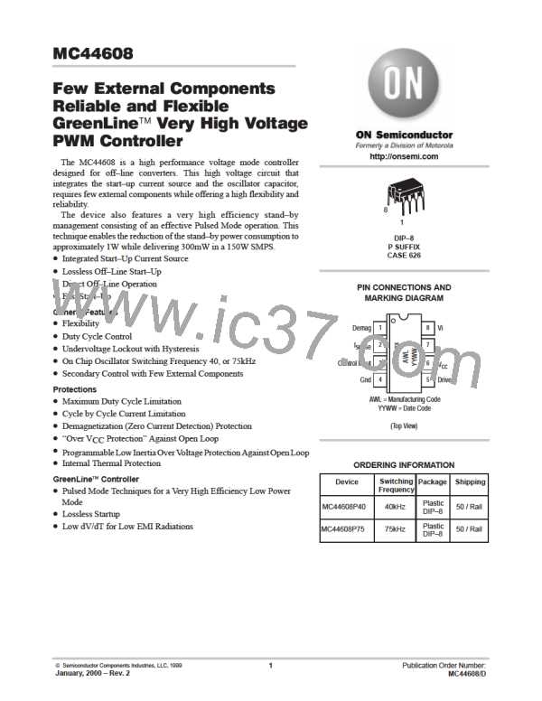
MC44608
EQUATION 7
1
d
BM
I
I
I
stup
ccS
I
G
1
k
k
S Stup
S L
I
I
stup
ccL
pin3
EQUATION 8
1
d
BM
I
G
1
I
1
k1
k
(k
)
S Stup
S L
I
stup
pin3
k2
I
stup
where: k1 = I
/I
ccs stup
k2 = I
I
ccL/ stup
= (V
k
k
–UVLO2)/(V
stup
–UVLO1)
–UVLO1)
S/Stup
stup
stup
= (UVLO1–UVLO2)/(V
S/L
PULSED MODE CURRENT SENSE CLAMPING LEVEL
Equations 9, 10, 11 and 12 allow the calculation of the Rcs value for the desired maximum current peak value during the
SMPS stand–by mode.
EQUATION 9
V
cs–th
(R
I
)
cs
cs
Ipk
stby
R
S
where: V
is the CS comparator threshold
cs–th
I
R
R
is the CS internal current source
is the sensing resistor
cs
S
is the resistor connected between pin 2 and R
cs
S
EQUATION 10
I
cs
1
1
R
cs
V
cs–th
Ipk
V
stby
cs–th
R
S
S
EQUATION 11
(R
Y
)
cs
cs–stby
Ipk
V
stby
cs–th
R
where: Y
= I /V
cs–stby cs cs–th
Taking into account the circuit propagation delay ( t ) and the Power Switch reaction time ( t ):
cs ps
EQUATION 12
1
(R
Y
)
V
( t
t
)
ps
cs
cs–stby
cs
in
Ipk
V
stby
cs–th
R
L
p
S
http://onsemi.com
10

 ONSEMI [ ONSEMI ]