AMIS-52150 Low-Power Transceiver with Clock and Data Recovery
Data Sheet
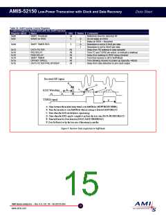
A kicker circuit stimulates the crystal oscillator circuit with oscillations close to the correct frequency. This reduces the time it takes for
the frequency to be locked. The receiver is on frequency and ready to receive the incoming signal much faster with the use of this
circuit. The Quick Start function is necessary when using the Sniff Mode. Table 25 lists the registers that function with Quick Start.
Refer to the AMIS application note “Quick Start Crystal Oscillator Circuit Operation and Setup” for more information.
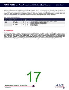
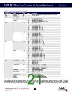
Table 25: Quick Start Control Registers
Quick Start Control Registers
Register (HEX)
0x03
0x0e
Name
Kicker Trim
Kick Config1
Bits
All
4
States
Comments
Trim the internal RC OSC to form a kick-start to the XTAL oscillator
Common mode clamp disabled (startup)
Common mode clamp enabled (normal)
Normal operation
0
1
0
1
Kick Config2
5
Continuous kick on
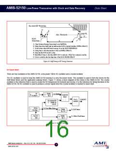
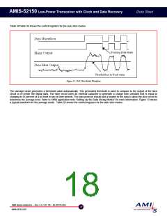
9.5 Data Detection
The RSSI circuit creates an analog voltage waveform (18mV/dB) that follows the signal strength of the RF signal. A data slice circuit
then samples that waveform to create the digitized data. The slice circuit in the AMIS-52150 can be programmed to operate in one of
three modes; DAC mode, average mode or peak mode. The DAC mode compares a fixed slice threshold value to the level in the slice
output. The digital data state is determined by the level of the slice output being above or below that fixed threshold. Refer to AMIS
application note “Setting Up the Data Slicing Modes” for more information. Figure 12 shows a typical waveform for the DAC mode.
AMI Semiconductor – Rev 4.0, Oct. 06 – M-20535-004
17
www.amis.com

 ONSEMI [ ONSEMI ]