AMIS-52150 Low-Power Transceiver with Clock and Data Recovery
Data Sheet
Table 24: Sniff Function Control Registers
Control Registers Associated with the Sniff Function
Register (HEX)
0x0b
0x0c
Name
SNIFF Threshold
WAKE on RSSI
Bits
All
5
States Comments
Reference level for detected RF
0
1
0
1
Do not wake on RSSI
Wake on RSSI > threshold
0x0d
SNIFF TIMER RES
3
Resolution is set to 0.5mS per step
Resolution is set to 64mS per step
Delay from RX wakeup to data sampled
0x13
0x16
0x18
0x19
0x1a
0x1b
DATA FILTER
IRQ DELAY
RSSI DELAY
SNIFF TIMER
OFFSET DWELL
DATA FILTER PRE-DIVIDER
All
All
All
All
All
All
Time I2C and TX/RX are active to indicate a wakeup
Delay from wakeup to RSSI being checked
Time that receiver is off in Sniff Mode
Time allowing receiver to power up (typically >40uS)
Delay from data detection to pre-clock output
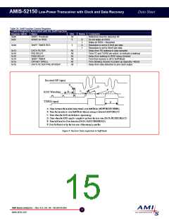
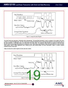
Figure 9: Receiver Data Acquisition in Sniff Mode
AMI Semiconductor – Rev 4.0, Oct. 06 – M-20535-004
15
www.amis.com

 ONSEMI [ ONSEMI ]