AMIS-52150 Low-Power Transceiver with Clock and Data Recovery
Data Sheet
9.0 Circuit Functional Description
The functions of the AMIS-52150 are presented in this section. These functions are:
• Receiver
• Transmitter
• Sniff
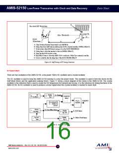
• Quick Start
• Data Detection
• Clock and Data Recovery
• Application Wakeup
• I2C Protocol
• Registers
• Alternative Wakeup
• Power on-Reset/Brownout
9.1 Receiver
RF signals often suffer from reflections along the path of propagation. These reflected signals arrive at the receiver antenna with
different phases or time delays. The different phases of the reflected signals causes the signal strength at the receiver to vary. This
variation can be large enough to cause the receiver to miss information. The AMIS-52150 sums the signals from the dual receiver
channels inside the data detection circuits. This reduces the effect of the multipath reflections. The receivers in the AMIS-52150 require
that the frequency be trimmed, the receiver oscillator frequency be tuned, the data rate filters be selected, and a signal threshold set as
shown in Table 20.
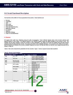
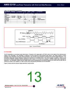
Table 21 lists some characteristic parameters for the receivers. Figure 7 shows a typical received data waveform.
Table 20: Receiver Control Registers
RX1 or RX2 Receiver Register Control
Register (HEX) Name
Bits
All
States Comments
Inverse relationship register
0x00
ANT1 trim
value to internal capacitance
Inverse relationship register
value to internal capacitance
0x01
ANT2 trim
All
0x05
0x0a
RX XTAL tune
Data threshold
All
All
Reference level for detecting data
logic state
0x0c
ANT1 enable
ANT2 enable
RX enable
0
1
0
1
0
1
0
Antenna port is off
Antenna port is on
Antenna port is off
Antenna port is on
Receiver is off
Receiver is on
1.1kHz
2.3kHz
5.2kHz
10.4kHz
1.18kHz
2.57kHz
7.0kHz
20.45kHz
Normal levels
Inverted
3
1
0x0f
Data filter
4,5,6
000
001
010
011
100
101
110
111
0
0x1e
TX/RX invert
5
1
AMI Semiconductor – Rev 4.0, Oct. 06 – M-20535-004
12
www.amis.com

 ONSEMI [ ONSEMI ]