AMIS-52150 Low-Power Transceiver with Clock and Data Recovery
Data Sheet
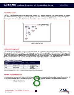
8.3 LPFILT, Loop Filter
The LPFILT pin connects the AMIS-52150 internal phase lock loop (PLL) frequency synthesizer to an external loop filter. An external
loop filter allows the design engineer to optimize the operation of the AMIS-52150 to meet the requirements of their product application.
For more information see the AMIS application note: “Extending to Frequencies outside the 403MHz Target”.
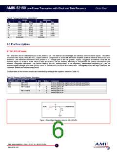
Figure 5: Typical Loop Filter
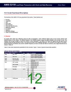
8.4 RSSI/BG, Analog Output
The RSSI/BG pin is used to output the signal from the RSSI circuits, the output of the voltage from the bandgap voltage reference or a
bypass capacitor node. The RSSI output is a true analog representation of the received signal level. The pin can also be programmed
to output the voltage of the bandgap voltage reference. When using the AMIS-52150 in the clock and data recovery mode, a capacitor
needs to be connected from the RSSI/BG pin to ground. A typical value for this capacitor is 2.2nF. Additional information on the CDR
function can be found later in this document. Table 12 presents the registers that control the function of the RSSI/BG pin.
Table 12: RSSVBG Pin Control Registers
RSSI Pin Definition Control Registers
Register
(HEX)
0x0e
Name
Bits States Comments
Bandgap on RSSI
RSSI Ext Amp
3
4
0
1
0
1
Normal operation
BG output on RSSI*
Tri-stated
0x1e
RSSI signal
*Note that device needs to be in RX, TX or crystal on moded for bandgap voltage to be present on pin.
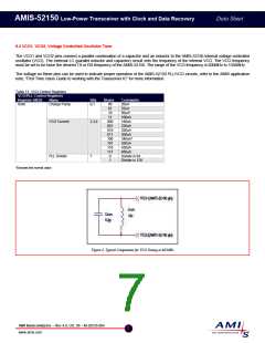
8.5 CREF, Current Reference Bias
A resistor must be connected to the AMIS-52150 CREF pin to provide a current bias to the internal bandgap voltage reference circuit. It
is critical that this resistor be a 33.2KΩ with one percent or better tolerance for proper operation of the bandgap voltage reference.
R(Bias) = 33.2KΩ (1%)
AMI Semiconductor – Rev 4.0, Oct. 06 – M-20535-004
8
www.amis.com

 ONSEMI [ ONSEMI ]