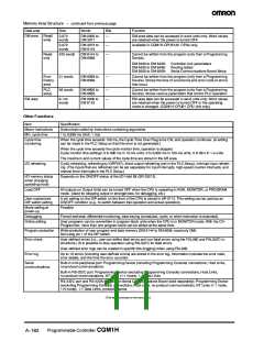
Other Functions -- continued from previous page
Item Specification
Serial communications modes
Built-in
Built-in
Serial communica-
tions board
mini-peripheral RS-232C
port
port
No
Programming
console bus
Connects to Programming Console.
YES
No
No
(pin 7 OFF)
Peripheral bus
Connects to a computer running CX-Programmer or other
Support Software. (Automatically used if the network type
is set to peripheral bus on the Support Software.)
YES
No
(pin 7 ON)
Host Link
Enables reading/writing CPU I/O memory or program using YES
YES
YES
(SYSMAC WAY)
Host Link commands. Computers running Support Soft-
ware or OMRON Programmable Terminals can also be
connected. PLC-initiated communications are possible.
(pin 7 ON)
No-protocol
1:1 data link
Enables sending or receiving up to 256 bytes of data with- YES
YES
YES
YES
YES
out a protocol or data conversion. A start code, end code,
and transmission delay can be set.
(pin 7 ON)
Enables 1:1 data link with a CQM1H, CQM1, CPM-series,
C200HX/HG/HE, C200HS, or SRM1 PLC.
No
No
No
NT links
Enables 1:1 or 1:N communications with OMRON Pro-
grammable Terminals without additional programming.
YES
YES
(1:1 and 1:N)
(1:1 only)
(1:1 and 1:N)
Protocol macros
Enables user-created protocols to communicate with es-
sential any device equipped with a serial communications
port (e.g., RS-232C). Standard protocols are also pro-
vided.
No
YES
Clock
Some Memory Cassette are equipped with a clock. (The time of the error will recorded if a clock is used.)
Input time constants Used to set the ON (or OFF) response times for DC Input modules.
Settings: 1, 2, 4, 8, 16, 32, 64, and 128 ms.
Power OFF
AC power supply: 10 to 25 ms (not fixed), DC power supply: 5 to 25 ms (not fixed)
detection time
Memory protection
Held Areas: Holding bits, contents of Data Memory and Extended Data Memory, and status of the counter
Completion Flags and present values.
If the I/O Hold Bit (SR 25212) is turned ON, and the PLC Setup is set to maintain the I/O Hold Bit status when
power is turned ON, the contents of the IR area and the LR area will be saved.
Commands to a host Host Link command responses can be sent to a computer connected via the Host Link System using the
computer TXD(—) (communications port output) instruction.
Remote program-
ming and monitoring programming and remote monitoring of the PLC through a Controller Link System. (This function is, however,
not supported for the serial communications ports on the Serial Communications Board.)
Host Link or peripheral bus communications via a CPU’s serial communications port can be used for remote
Program check
Battery life
Program is checked at the beginning of operation for items such as no END(01) instruction and instruction er-
rors. CX-Programmer can also check programs. (The level of program checking can be set.)
5 years at 25_C (Depends on the ambient temperature and power supply conditions. Min.: 1 yr)
Battery replacement must be performed within 5 minutes.
Errors from self-
diagnostics
CPU (watchdog timer), I/O verification, I/O bus, memory, FALS system (FALS execution or cycle monitor time
over), FAL system (FAL execution or PLC Setup error etc.), battery, cycle time over and communications port.
Other functions
Storage of number of times power has been interrupted. (Stored in AR area.)
A--163
Programmable Controller CQM1H

 OMRON [ OMRON ELECTRONICS LLC ]