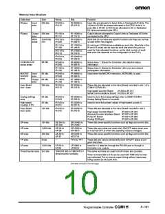
Memory Area Structure
Data area
IR area
Size
Words
Bits
Function
Input
area
256 bits
IR 000 to
IR 015
IR 00000 to
IR 01515
Input bits are allocated to Input Units or Dedicated I/O Units. The
16 bits in IR 000 are always allocated to the CPU’s built-in in-
puts. Bits in IR 001 to IR 015 are allocated to I/O or Dedicated
I/O Units connected to the CPU.
IR area
Output
area
256 bits
IR 100 to
IR 115
IR 10000 to
IR 11515
Output bits are allocated to Output Units or Dedicated I/O Units
connected to the CPU.
Work
areas
2,528 bits
min.
Work bits do not have any specific function and they can be free-
ly used within the program.
IR 016 to
IR 089
IR 01600 to
IR 08915
IR 116 to
IR 189
IR 11600 to
IR 18915
(A minimum 2,528 bits are available as work bits. Most bits in the
IR and LR areas can be used as work bits when they are not
used for their allocated functions, so the total number of avail-
able work bits depends on the configuration of the PLC.)
IR 216 to
IR 219
IR 21600 to
IR 21915
IR 224 to
IR 229
IR 22400 to
IR 22915
Controller Link
status areas
96 bits
IR 090 to
IR 095
IR 09000 to
IR 09515
Status Area 1: Stores the Controller Link data link status
information.
IR 190 to
IR 195
IR 19000 to
IR 19515
Status Area 2: Stores the Controller Link error and network
participation information.
MACRO
operand
area
Used when the MACRO instruction, MCRO(99), is used.
Input
area
64 bits
64 bits
256 bits
IR 096 to
IR 099
IR 09600 to
IR 09915
Output
area
IR 196 to
IR 199
IR 19600 to
IR 19915
Inner Board
slot 1 area
IR 200 to
IR 215
IR 20000 to
IR 21515
These bits are allocated to the Inner Board mounted in slot 1 of a
CQM1H-CPU51/61.
High-speed Counter Board:
IR 200 to IR 213
Serial Communications Board: IR 200 to IR 207
Analog settings
area
64 bits
32 bits
192 bits
IR 220 to
IR 223
IR 22000 to
IR 22315
Used to store the analog settings when a CQM1H-AVB41
Analog Setting Board is mounted.
High-speed
IR 230 to
IR 231
IR 23000 to
IR 23115
Used to store the present values of high-speed counter 0.
Counter, 0 PV
Inner Board
slot 2 area
IR 232 to
IR 243
IR 23200 to
IR 24315
These bits are allocated to the Inner Board mounted in slot 2.
High-speed Counter Board:
Absolute Encoder Interface Board: IR 232 to IR 239
Pulse I/O Board: IR 232 to IR 239
Analog I/O Board: IR 232 to IR 239
IR 232 to IR 243
SR area
HR area
AR area
TR area
LR area
184 bits
1,600 bits
448 bits
8 bits
SR 244 to
SR 255
SR 24400 to
SR 25507
These bits serve specific functions such as flags and control bits.
HR 00 to
HR 99
HR 0000 to
HR 9915
These bits store data and retain their ON/OFF status when pow-
er is turned OFF or when the operating mode is changed.
AR 00 to
AR 27
AR 0000 to
AR 2715
These bits serve specific functions such as flags and control bits.
—
TR 0 to TR 7
These bits are used to temporarily store ON/OFF status at pro-
gram branches.
1,024 bits
LR 00 to
LR 63
LR 0000 to
LR 6315
Used for 1:1 data link through the RS-232 port or through a
Controller Link module.
Timer/Counter area 512 bits
TIM/CNT 000 to TIM/CNT 511
(timer/counter numbers)
The same numbers are used for both timers and counters.
Timer numbers 000 to 015 can be used with TIMH(15) for inter-
rupt-refreshed PVs to ensure proper timing without inaccuracy
being caused by the cycle time.
(This table continues on the next page.)
A--161
Programmable Controller CQM1H

 OMRON [ OMRON ELECTRONICS LLC ]