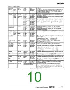
Memory Area Structure -- continued from previous page
Data area
DM area
Size
Words
Bits
—
Function
Read/
write
3,072
words
DM 0000 to
DM 3071
DM area data can be accessed in word units only. Word values
are retained when the power is turned OFF.
3,072
words
DM 3072 to
DM 6143
—
—
Available in CQM1H-CPU51/61 CPUs only.
Read-
only
425 words
DM 6144 to
DM 6568
Cannot be written from the program (only from a Programming
Device).
DM 6400 to DM 6409:
DM 6450 to DM 6499:
DM 6550 to DM 6559:
Controller Link parameters
Routing tables
Serial Communications Board Setup
Error
history
area
31 words
56 words
DM 6569 to
DM 6599
—
Cannot be written from the program (only from a Programming
Device). Stores the time of occurrence and error code of errors
that occur.
PLC
DM 6600 to
DM 6655
—
—
Cannot be written from the program (only from a Programming
Device). Stores various parameters that control PLC operation.
setup
EM area
6,144
words
EM 0000 to
EM 6143
EM area data can be accessed in word units only. Word values
are retained when the power is turned OFF or the operating
mode is changed. (CQM1H-CPU61 CPU Unit only.)
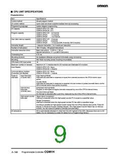
Other Functions
Item
Specification
Macro instructions
Min. cycle time
Subroutines called by instructions containing arguments.
1 to 9,999 ms (Unit: 1 ms)
Cycle time
monitoring
When the cycle time exceeds 100 ms, the Cycle Time Over Flag turns ON, and operation continues. (A setting
can be made in the PLC Setup so that this error is not generated.)
When the cycle time exceeds the cycle monitor time, operation is stopped.
Cycle monitor time settings: 0 to 990 ms in 10-ms units, 0 to 9,900 ms in 100-ms units, 0 to 99 s in 1-s units.
The maximum and current values of the cycle time are stored in the AR area.
I/O refreshing
Cyclic refreshing, refreshing by IORF(97), direct output refreshing (set in the PLC Setup), interrupt input refresh-
ing. (The inputs that are refreshed can be set separately for input interrupts, high-speed counter interrupts, and
interval timer interrupts in the PLC Setup.)
I/O memory status
when changing
operating mode
Depends on the ON/OFF status of the I/O Hold Bit (SR 25212).
Load OFF
All outputs on Output Units can be turned OFF when the CPU is operating in RUN, MONITOR, or PROGRAM
mode. (Used for stopping output in emergencies, for debugging, etc.)
User-customized
DIP switch setting
A pin setting on the DIP switch on the front of the CPU is stored in AR 0712. This setting can be used as an
ON/OFF condition (e.g., to switch between trial operation and actual operation).
Mode setting at
power-up
Possible
Debugging
Forced set/reset, differential monitoring, data tracing (scheduled, cyclic, or when instruction is executed).
Online editing
User programs can be overwritten in program-block units when the CPU is in MONITOR mode. With the CX-
Programmer, more than one program block can be edited at the same time.
Program protection
Error check
Write-protection of user program and data memory (DM 6144 to DM 6655: read-only DM):
Set using pin 1 of the DIP switch.
User-defined errors (i.e., user can define fatal errors and non-fatal errors using the FAL(06) and FALS(07) in-
structions.) (It is possible to stop operation using FALS(07) for fatal errors.
User-defined error logs can be created in specific bits (logging) when using FAL(06).
Error log
Up to 10 errors (including user-defined errors) are stored in the error log. Information includes the error code,
error details, and the time the error occurred.
Built-in mini-peripheral port: Programming Device (including Programming Console) connections, Host Links,
no-protocol communications
Serial
communications
Built-in RS-232C port: Programming Device (excluding Programming Console) connections, Host Links,
no-protocol communications, NT Links (1:1 mode), 1:1 Data LInks
RS-232C port and RS-422A/485 port on Serial Communications Board (sold separately): Programming Device
(excluding Programming Console) connections, Host Links, no-protocol communications, NT Links (1:1 mode,
1:N mode), 1:1 Data LInks, protocol macros
(This table continues on the next page.)
A--162
Programmable Controller CQM1H

 OMRON [ OMRON ELECTRONICS LLC ]