TDF8544
NXP Semiconductors
I2C-bus controlled 4 50 W power amplifier
8.2 I2C-bus data bytes
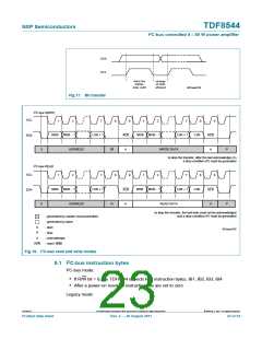
I2C-bus mode:
• If R/W = 1, the TDF8544 sends data bytes to the microprocessor
• All bits are reset after a read operation except DBx[D4] and DBx[D5] in DB1 to DB4.
Bit DBx[D2] in DB1 to DB4 is set after a read operation; see Section 7.5.1 and
Section 7.5.2.
• For explanation of AC and DC load detection bits, see Section 7.5.3
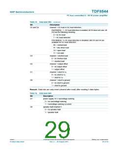
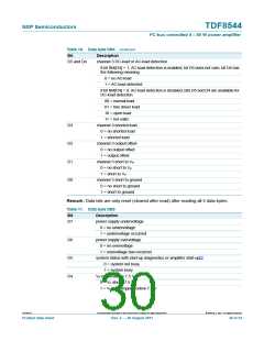
Table 13. Data byte DB1
Bit
Description
D7
temperature pre-warning
0 = no temperature pre-warning
1 = temperature pre-warning has occurred
speaker fault channel 2
D6
0 = no speaker fault, channel 2
1 = speaker fault, channel 2
channel 2 DC-load or AC-load detection
D5 and D4
if bit IB4[D4] = 1, AC-load detection is enabled, bit D5 does not care, bit D4 has
the following meaning:
0 = no AC-load
1 = AC-load detected
if bit IB4[D4] = 0, AC-load detection is disabled, bits D5 and D4 are available
for DC-load detection
00 = normal load
01 = line driver load
10 = open load
11 = not valid
D3
D2
D1
D0
channel 2 shorted load
0 = no shorted load
1 = shorted load
channel 2 output offset
0 = no output offset
1 = output offset
channel 2 short to VP
0 = no short to VP
1 = short to VP
channel 2 short to ground
0 = no short to ground
1 = short to ground
Remark: Data bits are only reset (cleared after read) after reading 5 data bytes.
TDF8544
All information provided in this document is subject to legal disclaimers.
© NXP B.V. 2011. All rights reserved.
Product data sheet
Rev. 2 — 29 August 2011
27 of 54

 NXP [ NXP ]