TDF8544
NXP Semiconductors
I2C-bus controlled 4 50 W power amplifier
switched off. If several channels have a short across the load at the same time, the
channels are switched on one by one to prevent high supply current switching with four
shorts across the load at the same time. The 15 ms cycle reduces power dissipation. To
prevent audible distortion, the channel with the short can be disabled via the I2C-bus.
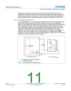
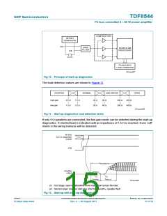
7.4.2 Loss-of-ground/loss of VP
Loss-of-ground/loss of VP is a double fault condition: the ground (or VP) wire of the set is
not connected and the ground (or VP) wire is connected to one of the loudspeaker
outputs. In this situation the supply capacitor in the set is charged through the body diode
of the output power transistor. This body diode (between the drain and source of the
power transistor) is always present in amplifiers with MOS output stages. The capacitor
charge current depends on the series impedance of the supply lines, the output
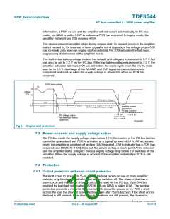
impedance of the loss-of-ground tester and the value of the capacitor; see Figure 7. To
simulate a worst-case condition, the loss-of-ground tester is equipped with a buffer
capacitor of 116 mF to simulate a very low output impedance. With an RS of 63 m, peak
currents of more than 70 A have been measured.
3
(2)
5
7
(1)
9
2200 μF
17
19
21
23
C
buffer
116 mF
V
P
NMOS
80N03L
V
pulse
R
S
Loss-of-ground tester
DUT in application
001aam695
(1) Capacitor can be 2200 F to 10000 F.
(2) Amplifier output stage.
Fig 7. Test circuit for loss-of-ground test
TDF8544
All information provided in this document is subject to legal disclaimers.
© NXP B.V. 2011. All rights reserved.
Product data sheet
Rev. 2 — 29 August 2011
11 of 54

 NXP [ NXP ]