TDF8544
NXP Semiconductors
I2C-bus controlled 4 50 W power amplifier
information, a POR occurs and the amplifier will not restart automatically. In I2C-bus
mode, pin DIAG is pulled LOW to indicate a POR has occurred. In legacy mode, the
amplifier restarts if pin STB remains HIGH.
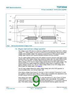
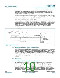
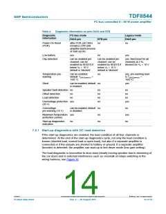
The device prevents amplifier plops during engine start. To prevent plops on the amplifier
output caused by, for instance, a tuner regulator out of regulation, the voltage on pin STB
can be made zero when an engine start is detected. Pin STB activates the fast mute,
suppressing disturbances at the amplifier inputs.
The built-in low battery voltage mute is the default, and in legacy mode is set to 5.5 V, but
can also be set to 7.2 V via the I2C-bus. If the low battery voltage mute is set to 7.2 V, the
amplifier activates fast mute (400 s) and enters the same cycle when the low VP mute
was set to 5.5 V: discharge of the ACGND and SVR capacitors when the mute is
completed and start-up when the supply voltage is above 8 V, when no POR has
occurred.
SVR clamp voltage
V
P
14
10
voltage
(V)
DC output voltage
7
6
3.5
UVP
amplifier re-start
SVR voltage/DC input voltage
(depends on
2
I C-bus content)
t (s)
DC voltage output
not filtered to ensure
headroom
t
(start-Vo(off))
t
(start-SVRoff)
001aam687
Fig 6. Engine start protection
7.3 Power-on reset and supply voltage spikes
If in I2C-bus mode the supply voltage drops below 4.5 V, the content of the I2C-bus latches
cannot be guaranteed and POR is activated at a typical VP level of 3.1 V. All latches are
reset, the amplifier is switched off and pin DIAG is pulled LOW to indicate that a POR has
occurred; see DB2[D7]. If IB1[D0] is set, the power-on flag is reset, pin DIAG is released
and the amplifier starts. In legacy mode a supply voltage drop below 6 V switches off the
amplifier. When the supply voltage is above 6 V the amplifier restarts if pin STB is still
enabled.
7.4 Protection
7.4.1 Output protection and short-circuit protection
If a short-circuit to ground, to VP or across the load occurs on one or more amplifier
outputs, only the channel with the short will be switched off. The channel that has a
short-circuit and the type of short-circuit can be read via the I2C-bus. If pin DIAG is
enabled for load fault information (IB2[D4] = 0) pin DIAG is pulled LOW. The window
protection prevents a restart of the channel with a short to ground or VP. With a short
across the load the channel is switched on again after 15 ms to check if the short across
the load is still present. If the short-circuit conditions are still present, the channel is
TDF8544
All information provided in this document is subject to legal disclaimers.
© NXP B.V. 2011. All rights reserved.
Product data sheet
Rev. 2 — 29 August 2011
10 of 54

 NXP [ NXP ]