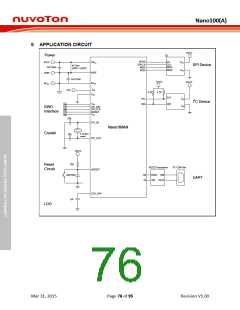
Nano100(A)
5.20 Analog to Digital Converter (ADC)
5.20.1 Overview
The Nano100 series contains one 12-bit successive approximation analog-to-digital converters (SAR
A/D converter) with 8 external input channels and 1 internal channel. The A/D converter supports
three operation modes: single, single-cycle scan and continuous scan mode, and can be started by
software, external STADC/PB.8 pin, timer event start.
Note that the I/O pins used as ADC analog input pins must configure the Pin Function (PA_L_MFP) to
ADC input and off digital function (GPIOA_OFFD) should be turned on before ADC function is
enabled.
5.20.2 Features
Analog input voltage range: 0~Vref (Max to 3.6V).
12-bit resolution and 8-bits accuracy is guaranteed.
Up to 8 external analog input channels (channel0 ~ channel7), and 1 internal channel
(channel10) converting four voltage sources (internal band-gap voltage, internal temperature
sensor output, AVDD, and AVSS).
Maximum ADC clock frequency is 16 MHz and each conversion is 21 clocks.
Three operating modes
Single mode: A/D conversion is performed one time on a specified channel.
Single-cycle scan mode: A/D conversion is performed one cycle on all specified channels
with the sequence from the lowest numbered channel to the highest numbered channel.
Continuous scan mode: A/D converter continuously performs Single-cycle scan mode until
software stops A/D conversion.
An A/D conversion can be started by
Software write 1 to ADST bit
External pin STADC
Selects one from four timer events (TMR0, TMR1, TMR2 and TMR3) that enable ADC and
transfer AD results by PDMA
Conversion results are held in data registers for each channel
Supports data registers to hold conversion results for each channel.
Supports A/D conversion End interrupt to indicate the end of A/D conversion.
Supports two digital comparators to compare conversion result with a specified value.
Supports digital comparator interrupt to indicate that conversion result meets setting condition.
Mar 31, 2015
Page 75 of 95
Revision V1.00

 NUVOTON [ NUVOTON ]