®
Numonyx™ StrataFlash Embedded Memory (J3-65nm)
12.2
Reset Specifications
Asserting RP# during a system reset is important with automated program/erase
devices because systems typically expect to read from flash memory when coming out
of reset. If a CPU reset occurs without a flash memory reset, proper CPU initialization
may not occur. This is because the flash memory may be providing status information,
instead of array data as expected. Connect RP# to the same active low reset signal
used for CPU initialization.
Also, because the device is disabled when RP# is asserted, it ignores its control inputs
during power-up/down. Invalid bus conditions are masked, providing a level of memory
protection.
Table 16: Power and Reset
Num
Symbol
Parameter
Min
Max
Unit
Notes
P1
t
RP# pulse width low
100
-
-
ns
1,2,3,4
1,3,4,7
1,3,4,7
1,4,5,6
PLPH
RP# low to device reset during erase
RP# low to device reset during program
VCC Power valid to RP# de-assertion (high)
25
25
-
P2
t
t
PLRH
VCCPH
-
µs
P3
300
Notes:
1.
2.
3.
4.
5.
6.
7.
These specifications are valid for all device versions (packages and speeds).
The device may reset if t is < t Min, but this is not guaranteed.
PLPH
PLPH
Not applicable if RP# is tied to VCC.
Sampled, but not 100% tested.
When RP# is tied to the VCC supply, device will not be ready until t
after VCC ≥ V
VCCPH
.
VCCPH
CCMIN
When RP# is tied to the VCCQ supply, device will not be ready until t
Reset completes within t
after VCC ≥ V
.
CCMIN
if RP# is asserted while no erase or program operation is executing.
PLPH
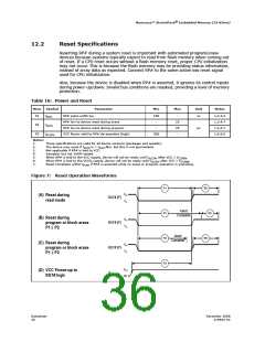
Figure 7: Reset Operation Waveforms
P1
P2
P2
P3
R5
VIH
VIL
(
A) Reset during
read mode
RST# [P]
RST# [P]
RST# [P]
VCC
Abort
R5
Complete
(B) Reset during
VIH
VIL
program or block erase
P1
≤
P2
Abort
Complete
R5
(C) Reset during
VIH
VIL
program or block erase
P1
≥
P2
VCC
0V
(D) VCC Power-up to
RST# high
Datasheet
36
December 2008
319942-02

 NUMONYX [ NUMONYX B.V ]