Voltage, Fan, and Temperature High/Low errors are slightly
more complex in their generation of INT# outputs. All of
these error bits are stored in the Interrupt Status Registers at
43h, 44h and the Interrupt Status Mirror Registers at 4Ch
and 4Dh. These inputs are gated by the Interrupt Mask
Registers and processed by the INT# state machine to gen-
erate the INT# output.
Functional Description (Continued)
•
THERM# Input: This is an active low interrupt that
would typically be generated by an external temperature
monitoring system. If the THERM# output is currently
inactive and this input is pulled low by an external circuit,
the THERM# Interrupt Status bit will be set. In addition,
the DAC output will be forced to full scale operation while
THERM# is pulled low by the external source. This allows
a separate thermal sensor to override the current fan
speed setting in an overtemperature situation not sensed
by the LM87. The DAC setting will return to normal when
the THERM# input is deactivated and the DAC setting
register is unaffected by the THERM# input condition.
Voltage and Fan error conditions are processed as follows.
Every time a round robin conversion cycle is completed, the
high/low limit comparisons for voltage and fan quantities are
updated. If a quantity is outside the limits, the appropriate
Interrupt Status Register bit will be set. If the corresponding
Interrupt Mask Register bit is 0, then the Status Bit will cause
the INT# output to be asserted. Reading the Interrupt Status
register will clear the Status Bit and cause the INT# output to
be deasserted. If the parameter is still outside the limits on
the next conversion, the status bit will again be set and it will
again cause an interrupt. If, on a subsequent conversion
cycle, the parameter returns within the High/Low limits be-
fore the Interrupt Status Registers are read, the Interrupt
Status bit will remain set and the INT# output will remain
asserted.
•
IRQ0-2: These are active low inputs from any type of
external interrupt source. If enabled via the Channel
Mode Register (16h) the INT# output will be activated
whenever these inputs are pulled low. Since there are no
dedicated ISR bits that correspond to the IRQ inputs, the
VID status bits can be read to determine which IRQ input
is active. Similarly, to mask off these inputs as interrupt
sources, they must be disabled via the Channel Mode
Register (16h).
Temperature High/Low errors are somewhat more compli-
cated. The internal temperature value is compared with the
Internal Temperature High and Low Limits in Registers 39h
and 3Ah (and with the Internal Temperature Hardware High
Limit in Registers 13h and 17h, see the next paragraph for
details). We will begin with the temperature value initially
within the High/Low limits and the corresponding Interrupt
Mask Bit = 0. If the temperature value rises above the high
limit, or below the low limit, the corresponding Interrupt
Status Register bit will be set. This will then cause an INT# to
be asserted. Reading the Interrupt Status Register will clear
the status bit and cause INT# to be deasserted. If the tem-
perature value remains above the high limit during subse-
quent conversion cycles, the Interrupt Status Bit will again be
set, but no new INT# will be generated from this source.
INT# may be reasserted if:
•
IRQ3-4: These are active high inputs from any type of
external interrupt source. If enabled via the Channel
Mode Register (16h) and Configuration Register 2 (4Ah),
the INT# output will be activated whenever these inputs
are driven high. Since there are no dedicated ISR bits
that correspond to the IRQ inputs, the VID status bits can
be read to determine which IRQ input is active. Similarly,
to mask off these inputs as interrupt sources, they must
be disabled via Configuration Register 2 (4Ah).
With the exception of the IRQ inputs and Hardware Tem-
perature errors, all interrupts are indicated in the two Inter-
#
rupt Status Registers. The INT output has two mask regis-
ters, and individual masks for each Interrupt. As described in
Section 3.3, the hardware Interrupt line can also be enabled/
disabled in the Configuration Register.
•
The temperature then transitions up or down through the
opposite limit to that originally exceeded.
#
The THERM interrupt output is dedicated to temperature
and therefore is only related to internal and external tem-
perature readings, and the Low, High and Hardware tem-
perature limits.
•
The original limit crossed is programmed to a new value
and on a subsequent conversion cycle, the converted
temperature is outside the new limit. This would cause
the corresponding Interrupt Status Bit to be set, causing
a new INT# event.
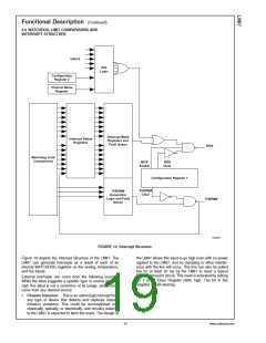
9.1 INT# Interrupts
The INT# system combines several groups of error signals
together into a common output. These groups are; IRQ
inputs, Voltage and Fan inputs, Temperature Values, and the
THERM# input. Each one of these groups or channels func-
tions a little differently.
•
An interrupt is generated by any other source, including
any other temperature error or the THERM# pin being
pulled low by an external signal.
The third group of signals that will generate INT# outputs are
Hardware Temperature errors, caused by temperatures ex-
ceeding the hardware limits stored at 13h, 14h, 17h, and
18h.The internal temperature value is compared with the
Internal Temperature Hardware High Limits in Registers 13h
and 17h. The external temperature values are compared
with the External Temperature Hardware High Limits in Reg-
isters 14h and 18h. The limits in Register 14h and 18h apply
equally to the values of both D1 and D2. Both temperature
values are individually compared with both limit values.
The IRQ inputs provide the least complicated INT# opera-
tion. The IRQ input block is enabled by setting bit 7of the
Channel Mode Register (16h) to 0. Then the individual inputs
are enabled by setting the corresponding IRQ Enable bits to
1. If an IRQ input is enabled, and subsequently an input
signal is asserted on that channel, the INT# output will be
asserted. During the interrupt service routine, the INT# out-
put can be deasserted in a number of ways. The INT#_Clear
bit can be set during the ISR to prevent further interrupts
from occurring. Then the IRQ enable bit for the particular
input can be cleared to prevent that channel from causing
further interrupts. At this point the INT#_Clear bit can be
cleared and no further interrupts would be issued from this
particular IRQ input. Once the signal causing the IRQ has
been removed, the enable bit for that IRQ channel could be
set again.
The only difference between the different Hardware Limit
registers is that by writing a 1 into Bit 1 of register 4Ah, the
contents of register 13h will be locked and cannot be repro-
grammed. Similarly, the contents of register 14h will be
locked by writing a 1 into Bit 2 of register 4Ah. The registers
can only be reprogrammed if Bit 7 of Configuration Register
www.national.com
20

 NSC [ National Semiconductor ]