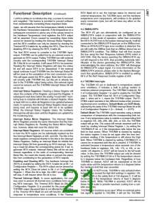
INT# Mask bit is set, the interrupt status for internal and
external temperature, the THERM# input, and the hardware
temperature error comparisons, will continue to be updated
every conversion cycle, but will not have any effect on the
INT# output.
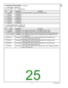
Functional Description (Continued)
1 (40h) is written to re-Initialize the chip, or power is removed
and reapplied. This feature is provided to prevent software
from unintentionally overwriting these important limits.
Again, we will assume that the temperature initially is below
the Hardware Temperature setpoints. If the temperature on a
subsequent conversion is above any of the values stored in
the Hardware Temperature Limit registers, the INT# output
will be asserted. Errors caused by exceeding these limits
cannot be cleared by reading the Interrupt Status Registers,
and the INT# condition can only be cleared by clearing the
Thermal INT# Enable bit, by setting the INT#_Clear bit or by
disabling INT# by clearing the INT#_Enable bit.
9.2 SMBALERT#
The INT# I/O pin can alternatively be configured as an
SMBALERT# output in conjunction with the SMBALERT#
protocol. In this mode of operation, rather than connecting
the INT# /ALERT# pin to the system interrupt inputs, it will be
connected to the SMBALERT# input pin on the SMBus host.
When an INT#/ALERT# type error condition is detected, this
pin will notify the SMBus host that an SMBus device has an
SMBALERT# condition. The SMBus host will then access
the bus using the Alert Response Address (ARA) which is
0001100b. Only the device asserting the SMBALERT# sig-
nal will respond to the ARA, thus providing automatic iden-
tification of the device generating the SMBALERT#. After
acknowledging the slave address, the LM87 will disengage
its SMBALERT# output signal. For more information on the
SMBALERT# protocol, please refer to the System Manage-
ment Bus specification. SMBALERT# is enabled by setting
Bit 6 of the Alert Response Enable register at 80h.
The final INT# source to consider is the THERM# input/
output. THERM# can be pulled low by an external source to
generate an INT# output. Pulling THERM# low with external
circuitry sets the corresponding THERM# Interrupt Status
Bit. If this bit is not masked, it will cause INT# to be asserted.
Reading the Interrupt Status Registers will clear the status
bit and will cause INT# to be deasserted. If the external
signal continues to pull THERM# low, the Interrupt Status Bit
will be reset at the completion of the next conversion cycle.
This will again assert the INT# output. Note that if the exter-
nal circuitry pulls THERM# low, but this pin is already low
due to the THERM# output being active, this external signal
cannot be sensed, and the THERM# Interrupt Status Bit will
not be set.
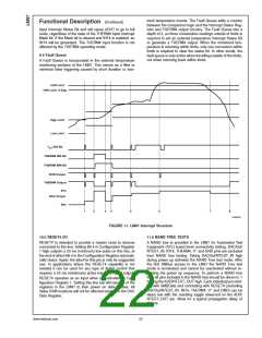
9.3 THERM# Interrupts
The THERM# I/O pin is dedicated to temperature related
error conditions. It includes a built in pull-up resistor to
minimize external components. The THERM# Enable bit, Bit
2 of Configuration Register 1 is used to enable the THERM#
output. The THERM# Clear bit, Bit 6 of Configuration Reg-
ister 1, when set to 1, clears the THERM# output. TheTH-
ERM# output operates in two different modes when process-
ing thermal error conditions, Default Mode and ACPI Mode,
selected by the state of the THERM# Interrupt Mode bit at Bit
3 of Configuration Register 2 (0 = Default, 1 = ACPI).
Interrupt Status Registers: Reading a Status Register will
return the contents of the Register, and reset the Register. A
subsequent read done before the analog “round-robin” moni-
toring loop is complete will indicate a cleared Register. Allow
at least 600 ms to allow all Registers to be updated between
reads. In summary, the Interrupt Status Register clears upon
being read, and requires at least 300 ms to be updated.
When the Interrupt Status Register clears, the hardware
interrupt line will also clear until the Registers are updated by
the monitoring loop.
Default Mode:The THERM# ouput operates using a simple
comparison of temperature with the corresponding limit val-
ues. If any temperature value is outside a corresponding limit
in registers 37h, 39h, 2Bh, 38h, 3Ah, or 2Ch, the THERM#
output will go low. The output will remain asserted until it is
reset by: reading Interrupt Status Register 1, by setting the
THERM#CLR bit, or if the temperature falls below the low
limit for that sensor. When THERM# is cleared by reading
the status register, it may be set again after the next tem-
perature reading, if the temperature is still above the high
limit. When THERM# is cleared by setting THERM#CLR, it
cannot be re-asserted until this bit is cleared. If THERM# is
activated because a temperature value exceeds one of the
hardware limits in registers 13h, 14h, 17h, or 18h, or ex-
ceeds 126 degrees C, AOUT will be forced to the full scale
value. In this case, the THERM# output can only be cleared
by setting the THERM#CLR bit or if the temperature returns
to 5 degrees below the hardware limit. Regardless of how
THERM# is cleared, AOUT will be maintained at the full
scale value until the temperature returns to 5 degrees below
the hardware limit that was exceeded.
Interrupt Status Mirror Registers: The Interrupt Status
Mirror Registers provide the same information that the Inter-
rupt Status Registers do. Reading the Status Mirror Regis-
ters, however, does not reset the status bits.
Interrupt Mask Registers: All sources which are combined
to form the INT# output can be individually masked via the
two Interrupt Mask Registers at 43h, and 44h. The bits in the
mask registers correspond directly to the bits in the Interrupt
Status Registers. Setting an Interrupt Mask bit inhibits that
Interrupt Status Bit from generating an INT# interrupt. Clear-
ing a mask bit allows the corresponding status bit, if set, to
generate INT# outputs. Interrupt Status Bits will be set and
cleared regardless of the state of corresponding Interrupt
Mask Bits, the mask bits merely allow or prevent the status
bits from contributing to the generation of INT# outputs.
Enabling and Clearing INT#: The hardware Interrupt line
#
(INT ) is enabled by setting the INT#_Enable bit at Bit 1 of
Configuration Register 1. The INT# output can be cleared by
setting the INT#_Clear bit which is Bit 3 of Configuration
Register 1. When this bit is high, the LM87 monitoring loop
will stop. It will resume when the bit is low.
ACPI Mode: In ACPI mode, THERM# is only activated when
temperatures exceed the high limit settings in registers 13h,
14h, 17h, 18h or the safety limit of 126 degrees C. It will be
de-asserted if the temperature returns at least 5 degrees
below the limit. While THERM# is asserted, AOUT will be
driven to full scale to provide maximum cooling from a vari-
able speed fan.
Thermal Interrupt Mask: In some applications, the user
may want to prevent all thermal error conditions from caus-
ing INT# interrupts. The Thermal INT# Mask bit (Bit 0 of
Configuration Register 2) is provided for this purpose. The
THERM# output discussed later is not affected by the status
of the Thermal INT# Mask bit and will function normally in
response to temperature error conditions. If the Thermal
THERM# also functions as an input. When an external active
low signal is applied to THERM#, it will set the THERM#
21
www.national.com

 NSC [ National Semiconductor ]