Functional Description (Continued)
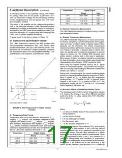
Temperature
Digital Output
Binary
Hex
00h
FFh
E7h
D8h
1 second) excursion to full operating voltage, then reduce
the voltage. Most fans do not operate at all below 5 to 7
volts. At those lower voltages the fan will simply consume
current, dissipate power, and not operate, and such condi-
tions should be avoided.
+0˚C
−1.0˚C
−25˚C
−40˚C
0000 0000
1111 1111
1110 0111
1101 1000
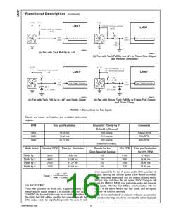
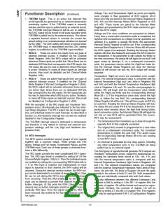
The output of the amplifier can be configured to provide a
high or low side pass transistor. A high side pass transistor
simplifies the coupling of tachometer outputs to the tachom-
eter inputs of the LM87 since the fan remains grounded. Low
side drive will require AC coupling along with clamping at the
LM87 input to prevent negative excursions.
8.2 Internal Temperature Measurement
The LM87 internal temperature is monitored using a junction
type temperature sensor.
A typical circuit for fan drive is shown in Figure 13.
8.3 Remote Temperature Measurement
The LM87 monitors the temperature of remote semiconduc-
tor devices using the p-n junction temperature sensing prin-
cipal. Up to two remote IC, diode or bipolar transistor tem-
peratures can be monitored. The remote measurement
channels have been optimized to measure the remote diode
of a Pentium II processor. A discrete diode or bipolar tran-
sistor can also be used to sense the temperature of external
objects or ambient air. The 2N3904 NPN transistor base
emitter junction performs well in this type of application.
When using a 2N3904, the collector should be connected to
the base to provide a device that closely approximates the
characteristics of the Pentium II PNP monitoring diode.
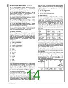
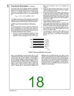
8.0 TEMPERATURE MEASUREMENT SYSTEM
The LM87 temperature sensor(s) and ADC produce 8-bit
two’s-complement temperature data. One internal diode
junction temperature, and up to two external junction tem-
peratures can be monitored. A digital comparator compares
the temperature data to the user-programmable High, Low,
and Hardware Limit setpoints, and Hysteresis values.
When using two external 2N3904 sensors, the D− inputs
should be connected together. This provides the best pos-
sible accuracy by compensating for differences between the
2N3904 and Pentium II sensors.
During each conversion cycle, the remote monitoring inputs
perform an external diode fault detection sequence. If the D+
input is shorted to VCC or floating then the temperature
reading will be +127˚C, and bit 6 or bit 7 of Interrupt Status
Register 2 will be set. If D+ is shorted to GND or D−, the
temperature reading will be 0˚C and bit 6 or 7 of Interrupt
Status Register 2 will not be set.
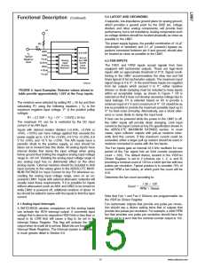
8.4 Accuracy Effects of Diode Non-Ideality Factor
The technique used in today’s remote temperature sensors
is to measure the change in VBE at two different operating
points of a diode. For a bias current ratio of N:1, this differ-
ence is given as:
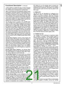
10099524
(Non-Linear Scale for Clarity)
FIGURE 8. 8-bit Temperature-to-Digital Transfer
Function
where:
•
η is the non-ideality factor of the process the diode is
manufactured on,
8.1 Temperature Data Format
•
•
•
•
q is the electron charge,
Temperature data can be read from the Temperature, THIGH
setpoint, TLOW setpoint, and Hardware Temperature limit
registers; and written to the THIGH setpoint, TLOW setpoint,
and Hardware Temperature limit registers. THIGH setpoint,
TLOW setpoint, Hardware Temperature Limit, and Tempera-
ture data is represented by an 8-bit, two’s complement word
with an LSB (Least Significant Bit) equal to 1˚C:
k is the Boltzmann’s constant,
N is the current ratio,
T is the absolute temperature in ˚K.
The temperature sensor then measures ∆VBE and converts
to digital data. In this equation, k and q are well defined
universal constants, and N is a parameter controlled by the
temperature sensor. The only other parameter is η, which
depends on the diode that is used for measurement. Since
∆VBE is proportional to both η and T, the variations in η
cannot be distinguished from variations in temperature.
Since the non-ideality factor is not controlled by the tempera-
ture sensor, it will directly add to the inaccuracy of the
sensor. For the Pentium II Intel specifies a 1% variation in
Temperature
Digital Output
Binary
Hex
7Dh
19h
01h
+125˚C
+25˚C
0111 1101
0001 1001
0000 0001
+1.0˚C
17
www.national.com

 NSC [ National Semiconductor ]