µPD75304B,75306B,75308B
8. RESET FUNCTION
The µPD75308B is reset and the hardware is initialized as shown in Table 8-1 by RESET input. The reset
operation timing is shown in Fig. 8-1.
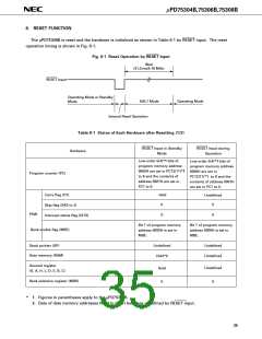
Fig. 8-1 Reset Operation by RESET Input
Wait
(31.3 ms/4.19 MHz)
RESET Input
Operating Mode or Standby
Mode
HALT Mode
Operating Mode
Internal Reset Operation
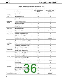
Table 8-1 Status of Each Hardware after Resetting (1/2)
RESET Input in Standby
RESET Input during
Operation
Hardware
Mode
Low-order 5(4)*1 bits of
program memory address
0000H are set in PC12(11)*1
to 8 and the contents of
address 0001H are set in
PC7 to 0.
Low-order 5(4)*1 bits of
program memory address
0000H are set in
Program counter (PC)
Carry flag (CY)
PC12(11)*1 to 8 and the
contents of address 0001H
are set in PC7 to 0.
Held
0
Undefined
0
Skip flag (SK0 to 2)
PSW
0
0
Interrupt status flag (IST0)
Bit 7 of program memory
address 0000H is set in
MBE.
Bit 7 of program memory
address 0000H is set in
MBE.
Bank enable flag (MBE)
Undefined
Stack pointer (SP)
Undefined
Undefined
Data memory (RAM)
Held*2
General register
Undefined
0
Held
0
(X, A, H, L, D, E, B, C)
Bank selection register (MBS)
*
1. Figures in parentheses apply to the µPD75304B.
2. Data of data memory addresses 0F8H to 0FDH becomes undefined by RESET input.
35

 NEC [ NEC ]