µPD75304B,75306B,75308B
5.9 BIT SEQUENTIAL BUFFER ..... 16 BITS
The bit sequential buffer is special data memory for bit manipulations and can be used easily particularly for
bit manipulations where addresses and bit specifications are changed sequentially, so it is convenient for
processing data with long bit lengths bit-wise.
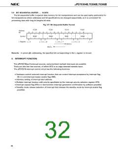
Fig. 5-8 Bit Sequential Buffer Format
FC3H
2
FC2H
2
FC1H
3
FC0H
3
Address
Bit
3
1
0
3
1
0
2
1
0
2
1
0
Symbol
BSB3
BSB2
BSB1
BSB0
L Register
L = F
L = C L = B
L = 8 L = 7
L = 4 L = 3
L = 0
DECS L
INCS L
Remarks In pmem.@L addressing, the specified bit corresponding to the L register is moved.
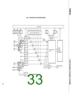
6. INTERRUPT FUNCTION
The µPD75218has 8 interrupt sources, and prioritized multiple interrupts are possible.
There are also two test sources, of which INT2 is an edge-detected testable input.
The µPD75218 interrupt control circuit has the following functions
• Hardware control vectored interrupt function that can control interrupt acceptance by interrupt flag
(IE×××) and interrupt master enable flag (IME).
• Arbitrary setting of interrupt start address.
• Multiple interrupt function with priority specifiable by the interrupt priority selection register (IPS).
• Interrupt request flag (IRQ×××) test function (interrupt generation confirmation by software possible).
• Standby mode release (selection of interrupt that releases the standby mode by interrupt enable flag
possible).
32

 NEC [ NEC ]