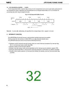
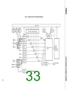
Fig. 6-1 Interrupt Control Circuit Block Diagram
Internal Bus
2
1
3
IM2
IM1
IM0
IME
IST0
Interrupt Enable Flag (IEXXX
)
Decoder
INT
BT
IRQBT
IRQ4
Both Edges
Detection
Circuit
INT4
/P00
VRQn
Edge
INT0
/P10
Detection
Circuit
IRQ0
*
Vector
Table
Address
Generator
Edge
INT1
/P11
IRQ1
Detection
Circuit
Priority Control
Circuit
INTCSI
IRQCSI
IRQT0
IRQW
IRQ2
INTT0
INTW
µ
Rising Edge
Detection
Circuit
INT2
/P12
Standby Release
Signal
KR0/P60
KR7/P73
Falling Edge
Detection
Circuit
IM2
*
Noise elimination circuit

 NEC [ NEC ]