µPD703100A-33, 703100A-40, 703101A-33, 703102A-33
11. SERIAL INTERFACE FUNCTION
The serial interface function provides two 6-channel serial interfaces.
Up to four channels can be used at the same time.
(1) Asynchronous serial interface (UART0 and UART1): 2 channels
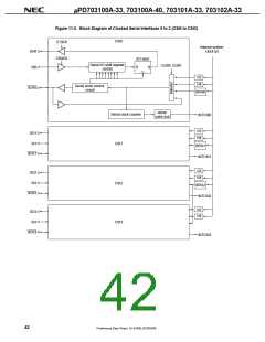
(2) Clocked serial interface (CSI0 to CSI3): 4 channels
Caution UART0 and CSI0 share a pin, as do UART1 and CSI1. One or the other of each pair can be
selected via a register (ASIM00, ASIM10).
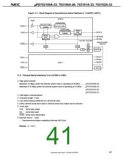
11.1 Asynchronous Serial Interfaces 0, 1 (UART0, UART1)
{ Transfer rate
150 bps to 76800 bps (using the dedicated baud rate generator when the internal system clock is
33 MHz)
Maximum 4.125 Mbps (using the φ/2 clock when the internal system clock is 33 MHz)
{ Full duplex communications
On-chip receive buffer (RXBn)
{ 2-pin configuration
TXDn: Transmit data output pin
RXDn: Receive data input pin
{ Receive error detection functions
•
•
•
Parity error
Framing error
Overrun error
{ Interrupt sources: 3 types
•
•
•
Receive error interrupt (INTSERn)
Receive completion interrupt (INTSRn)
Transmission completion interrupt (INTSTn)
{ The character length of transmission/reception data is specified by the ASIMn0 and ASIMn1 registers.
{ Character length
7, 8 bits
9 bits (when adding an expansion bit)
{ Parity function: odd, even, 0, none
{ Transmission stop bit: 1, 2 bits
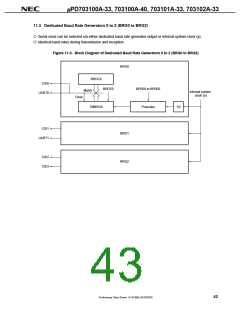
{ On-chip dedicated baud rate generator
{ Serial clock (SCKn) output function
Remark n = 0, 1
40
Preliminary Data Sheet U14168EJ2V0DS00

 NEC [ NEC ]