CHAPTER 14 INTERRUPT FUNCTIONS
(6) Key return mode register 00 (KRM00)
This register sets the pin that detects a key return signal (falling edge of port 0).
KRM00 is set with a 1-bit or 8-bit memory manipulation instruction.
RESET input sets KRM00 to 00H.
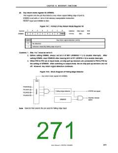
Figure 14-7. Format of Key Return Mode Register 00
7
0
6
0
5
0
4
0
3
0
2
0
1
0
0
Symbol
KRM00
Address
FFF5H
After reset
00H
R/W
R/W
KRM000
KRM000
Key return signal detection control
0
1
No detection
Detection (detecting falling edge of port 0)
Cautions 1. Bits 1 to 7 must be set to 0.
2. Before setting KRM00, always set bit 6 of MK1 (KRMK00 = 1) to disable interrupts. After
setting KRM00, clear KRMK00 after clearing bit 6 of IF1 (KRIF00 = 0) to enable interrupts.
3. When P00 to P03 are in input mode, on-chip pull-up resistors are connected to P00 to P03 by
the setting of KRM000. After switching to output mode, the on-chip pull-up resistors are cut
off. However, key return signal detection continues.
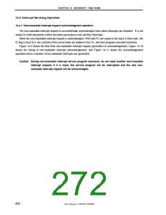
Figure 14-8. Block Diagram of Falling Edge Detector
Key return mode register 00 (KRM00)
Note
P00/KR0
P01/KR1
P02/KR2
P03/KR3
KRIF00 set signal
Falling edge detector
KRMK00
Standby release
signal
Note Selector that selects the pin used for falling edge input
User’s Manual U15075EJ1V0UM00
271

 NEC [ NEC ]