CHAPTER 14 INTERRUPT FUNCTIONS
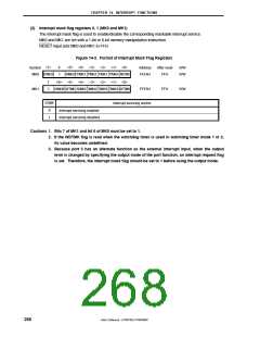
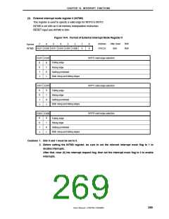
(3) External interrupt mode register 0 (INTM0)
This register is used to specify a valid edge for INTP0 to INTP2.
INTM0 is set with an 8-bit memory manipulation instruction.
RESET input sets INTM0 to 00H.
Figure 14-4. Format of External Interrupt Mode Register 0
Address
FFECH
After reset
00H
R/W
R/W
7
6
5
4
3
2
1
0
0
0
Symbol
INTM0
ES21 ES20 ES11 ES10 ES01 ES00
ES21 ES20
INTP2 valid edge selection
INTP1 valid edge selection
INTP0 valid edge selection
Falling edge
0
0
1
1
0
1
0
1
Rising edge
Setting prohibited
Both rising and falling edges
ES11 ES10
0
0
1
1
0
1
0
1
Falling edge
Rising edge
Setting prohibited
Both rising and falling edges
ES00
ES01
0
0
1
1
0
1
0
1
Falling edge
Rising edge
Setting prohibited
Both rising and falling edges
Cautions 1. Bits 0 and 1 must be set to 0.
2. Before setting the INTM0 register, be sure to set the relevant interrupt mask flag to 1 to
disable interrupts.
After that, clear (0) the interrupt request flag, then set the interrupt mask flag to 0 to enable
interrupts.
User’s Manual U15075EJ1V0UM00
269

 NEC [ NEC ]