CHAPTER 14 INTERRUPT FUNCTIONS
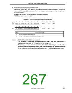
(2) Interrupt mask flag registers 0, 1 (MK0 and MK1)
The interrupt mask flag is used to enable/disable the corresponding maskable interrupt service.
MK0 and MK1 are set with a 1-bit or 8-bit memory manipulation instruction.
RESET input sets MK0 and MK1 to FFH.
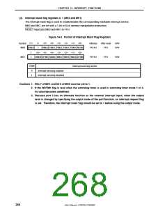
Figure 14-3. Format of Interrupt Mask Flag Registers
<7>
6
1
<5> <4> <3> <2> <1> <0>
SRMK20 PMK3 PMK2 PMK1 PMK0 WDTMK
Address
FFE4H
After reset
FFH
R/W
R/W
Symbol
MK0
STMK20
7
1
<6> <5> <4> <3> <2> <1> <0>
MK1
KRMK00 WTMK ADMK0 TMMK40 TMMK30 TMMK20 WTIMK
FFE5H
FFH
R/W
XXMK
Interrupt servicing control
0
1
Interrupt servicing enabled
Interrupt servicing disabled
Cautions 1. Bits 7 of MK1 and bit 6 of MK0 must be set to 1.
2. If the WDTMK flag is read when the watchdog timer is used in watchdog timer mode 1 or 2,
its value becomes undefined.
3. Because port 3 has an alternate function as the external interrupt input, when the output
level is changed by specifying the output mode of the port function, an interrupt request flag
is set. Therefore, the interrupt mask flag should be set to 1 before using the output mode.
268
User’s Manual U15075EJ1V0UM00

 NEC [ NEC ]