CHAPTER 14 INTERRUPT FUNCTIONS
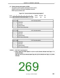
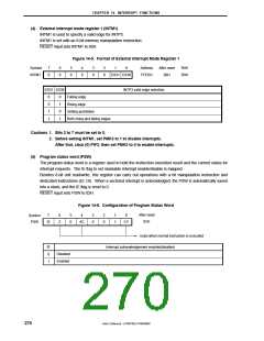
(4) External interrupt mode register 1 (INTM1)
INTM1 is used to specify a valid edge for INTP3.
INTM1 is set with an 8-bit memory manipulation instruction.
RESET input sets INTM1 to 00H.
Figure 14-5. Format of External Interrupt Mode Register 1
Symbol
INTM1
7
0
6
0
5
0
4
0
3
0
2
0
1
0
Address
FFEDH
After reset
00H
R/W
R/W
ES31 ES30
ES31 ES30
INTP3 valid edge selection
0
0
1
1
0
1
0
1
Falling edge
Rising edge
Setting prohibited
Both rising and falling edges
Cautions 1. Bits 2 to 7 must be set to 0.
2. Before setting INTM1, set PMK3 to 1 to disable interrupts.
After that, clear (0) PIF3, then set PMK3 to 0 to enable interrupts.
(5) Program status word (PSW)
The program status word is a register used to hold the instruction execution result and the current status for
interrupt requests. The IE flag to set maskable interrupt enable/disable is mapped.
Besides 8-bit unit read/write, this register can carry out operations with a bit manipulation instruction and
dedicated instructions (EI, DI). When a vectored interrupt is acknowledged, the PSW is automatically saved
into a stack, and the IE flag is reset to 0.
RESET input sets PSW to 02H.
Figure 14-6. Configuration of Program Status Word
After reset
02H
7
6
Z
5
0
4
3
0
2
0
1
1
0
Symbol
PSW
IE
AC
CY
Used when normal instruction is executed
IE
0
Interrupt acknowledgement enabled/disabled
Disabled
Enabled
1
270
User’s Manual U15075EJ1V0UM00

 NEC [ NEC ]