CHAPTER 14 INTERRUPT FUNCTIONS
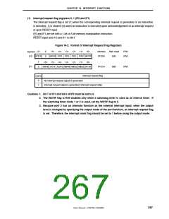
(1) Interrupt request flag registers 0, 1 (IF0 and IF1)
The interrupt request flag is set (1) when the corresponding interrupt request is generated or an instruction
is executed. It is cleared (0) when an instruction is executed upon acknowledgement of an interrupt request
or upon RESET input.
IF0 and IF1 are set with a 1-bit or 8-bit memory manipulation instruction.
RESET input sets IF0 and IF1 to 00H.
Figure 14-2. Format of Interrupt Request Flag Registers
Address
FFE0H
After reset
00H
R/W
R/W
<7>
6
0
<5> <4> <3> <2> <1> <0>
SRIF20 PIF3 PIF2 PIF1 PIF0 WDTIF
Symbol
IF0
STIF20
7
0
<6> <5> <4> <3> <2> <1> <0>
KRIF00 WTIF ADIF0 TMIF40 TMIF30 TMIF20 WTIIF
IF1
FFE1H
00H
R/W
Interrupt request flag
XXIFX
0
1
No interrupt request signal is generated
Interrupt request signal is generated; Interrupt request state
Cautions 1. Bit 7 of IF1 and bit 6 of IF0 must be set to 0.
2. The WDTIF flag is R/W enabled only when a watchdog timer is used as an interval timer. If
the watchdog timer mode 1 or 2 is used, set the WDTIF flag to 0.
3. Because port 3 has an alternate function as the external interrupt input, when the output
level is changed by specifying the output mode of the port function, an interrupt request flag
is set. Therefore, the interrupt mask flag should be set to 1 before using the output mode.
User’s Manual U15075EJ1V0UM00
267

 NEC [ NEC ]