CHAPTER 14 INTERRUPT FUNCTIONS
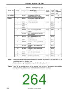
Table 14-1. Interrupt Source List
Interrupt Type
PriorityNote 1
Interrupt Source
Trigger
Internal/
External
Vector
Table
Basic
Configuration
TypeNote 2
Name
Address
0004H
Non-maskable
Maskable
−
INTWDT
INTWDT
Watchdog timer overflow (with
Internal
(A)
(B)
(C)
watchdog timer mode 1 selected)
0
Watchdog timer overflow (with interval
timer mode selected)
1
2
3
4
5
INTP0
INTP1
INTP2
INTP3
INTSR20
Pin input edge detection
External
0006H
0008H
000AH
000CH
000EH
End of serial interface 20 UART
reception
Internal
(B)
INTCSI20
INTST20
End of serial interface 20 3-wire SIO
transfer reception
6
End of serial interface 20 UART
transmission
0012H
7
8
INTWTI
Interval timer interrupt
0014H
0016H
INTTM90
Generation of match signal of 16-bit
timer 90
9
INTTM50
INTTM60
Generation of match signal of 8-bit
timer 50
0018H
001AH
10
Generation of match signal of 8-bit
timer 60
11
12
13
INTAD0
INTWT
End of A/D conversion signal
Watch timer interrupt
001CH
001EH
0020H
INTKR00
Key return signal detection
External
(C)
Notes 1. Priority is the priority order when several maskable interrupts are generated at the same time. 0 is the
highest order and 13 is the lowest order.
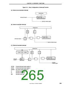
2. Basic configuration types (A) to (C) correspond to (A) to (C) in Figure 14-1.
Remark There are two interrupt sources for the watchdog timer (INTWDT): non-maskable and maskable
interrupts (internal). Either one (but not both) should be selected for actual use.
264
User’s Manual U15075EJ1V0UM00

 NEC [ NEC ]