CHAPTER 13 LCD CONTROLLER/DRIVER
13.1 LCD Controller/Driver Functions
The functions of the LCD controller/driver of the µPD789426, 789436, 789446, and 789456 Subseries are as
follows.
(1) Automatic output of segment and common signals based on automatic display data memory read
(2) Two different display modes:
• 1/3 duty (1/3 bias)
• 1/4 duty (1/3 bias)
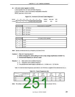
(3) Four different frame frequencies, selectable in each display mode
(4) Operation with a subsystem clock
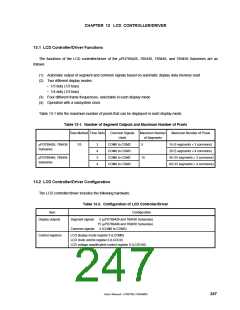
Table 13-1 lists the maximum number of pixels that can be displayed in each display mode.
Table 13-1. Number of Segment Outputs and Maximum Number of Pixels
Bias Method Time Slots
Common Signals
Used
Maximum Number
of Segments
Maximum Number of Pixels
µPD789426, 789436
1/3
3
4
3
4
COM0 to COM2
COM0 to COM3
COM0 to COM2
COM0 to COM3
5
15 (5 segments × 3 commons)
20 (5 segments × 4 commons)
45 (15 segments × 3 commons)
60 (15 segments × 4 commons)
Subseries
µPD789446, 789456
15
Subseries
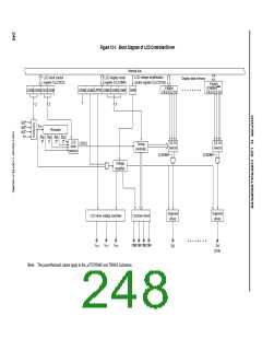
13.2 LCD Controller/Driver Configuration
The LCD controller/driver includes the following hardware.
Table 13-2. Configuration of LCD Controller/Driver
Item
Configuration
Display outputs
Segment signals: 5 (µPD789426 and 789436 Subseries)
15 (µPD789446 and 789456 Subseries)
Common signals: 4 (COM0 to COM3)
Control registers
LCD display mode register 0 (LCDM0)
LCD clock control register 0 (LCDC0)
LCD voltage amplification control register 0 (LCDVA0)
User’s Manual U15075EJ1V0UM00
247

 NEC [ NEC ]