CHAPTER 12 SERIAL INTERFACE 20
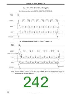
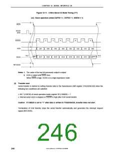
Figure 12-11. 3-Wire Serial I/O Mode Timing (7/7)
(xii) Slave operation (when DAP20 = 1, CKP20 = 1, SSE20 = 1)
SS20
SIO20
write
SCK20
SI20
1
2
3
4
5
6
7
8
DI7
DI6
DI5
DI4
DI3
DI2
DI1
DI0
Hi-Z
Hi-Z
DO0Note 2
Note 1
DO7
DO6
DO5
DO4
DO3
DO2
DO1
SO20
INTCSI20
Notes 1. The value of the last bit previously output is output.
2. DO0 is output until SS20 rises.
When SS20 is high, SO20 is in a high-impedance state.
(3) Transfer start
Serial transfer is started by setting transfer data to the transmission shift register (TXS20/SIO20) when the
following two conditions are satisfied.
• Bit 7 (CSIE20) of serial operation mode register 20 (CSIM20) = 1
• Internal serial clock is stopped or SCK20 is high after 8-bit serial transfer.
Caution If CSIE20 is set to “1” after data is written to TXS20/SIO20, transfer does not start.
Termination of 8-bit transfer stops the serial transfer automatically and generates the interrupt request
signal (INTCSI20).
User’s Manual U15075EJ1V0UM00
246

 NEC [ NEC ]