CHAPTER 12 SERIAL INTERFACE 20
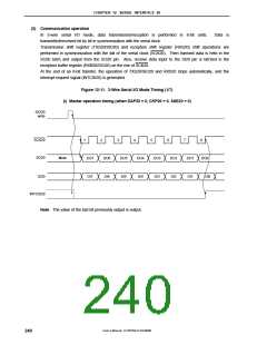
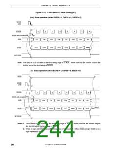
Figure 12-11. 3-Wire Serial I/O Mode Timing (5/7)
(viii) Slave operation (when DAP20 = 1, CKP20 = 0, SSE20 = 0)
SIO20
write
1
2
3
4
5
6
7
8
SCK20
SIO20 write (master)Note
SI20
DI7
DI6
DI5
DI4
DI3
DI2
DI1
DI0
DO7
DO6
DO5
DO4
DO3
DO2
DO1
DO0
SO20
INTCSI20
Note The data of SI20 is loaded at the first falling edge of SCK20. Make sure that the master outputs the
first bit before the first falling of SCK20.
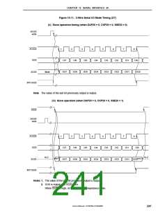
(ix) Slave operation (when DAP20 = 1, CKP20 = 0, SSE20 = 1)
SS20
SIO20
write
SCK20
1
2
3
4
5
6
7
8
SIO20 write (master)Note 1
SI20
DI7
DI6
DI5
DI4
DI3
DI2
DI1
DI0
Hi-Z
Hi-Z
Note 2
DO7
DO6
DO5
DO4
DO3
DO2
DO1
DO0
SO20
INTCSI20
Notes 1. The data of SI20 is loaded at the first falling edge of SCK20. Make sure that the master outputs
the first bit before the first falling of SCK20.
2. SO20 is high until SS20 rises after completion of DO0 output. When SS20 is high, SO20 is in a
high-impedance state.
User’s Manual U15075EJ1V0UM00
244

 NEC [ NEC ]