CHAPTER 12 SERIAL INTERFACE 20
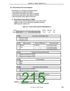
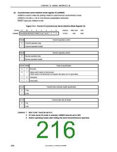
(2) Asynchronous serial interface mode register 20 (ASIM20)
ASIM20 is used to make the settings related to asynchronous serial interface mode.
ASIM20 is set with a 1-bit or 8-bit memory manipulation instruction.
RESET input sets ASIM20 to 00H.
Figure 12-4. Format of Asynchronous Serial Interface Mode Register 20
Symbol <7> <6>
5
4
3
2
1
0
0
0
Address
FF70H
After reset
00H
R/W
R/W
ASIM20 TXE20 RXE20 PS201 PS200 CL20 SL20
TXE20
Transmit operation control
0
1
Transmit operation stop
Transmit operation enable
RXE20
Receive operation control
0
1
Receive operation stop
Receive operation enable
PS201 PS200
Parity bit specification
0
0
0
1
No parity
Always add 0 parity at transmission.
Parity check is not performed at reception (No parity error is generated).
1
1
0
1
Odd parity
Even parity
CL20
Transmit data character length specification
0
1
7 bits
8 bits
SL20
Transmit data stop bit length
0
1
1 bit
2 bits
Cautions 1. Bits 0 and 1 must be set to 0.
2. If 3-wire serial I/O mode is selected, ASIM20 must be set to 00H.
3. Switch operating modes after halting the serial transmit/receive operation.
User’s Manual U15075EJ1V0UM00
216

 NEC [ NEC ]