CHAPTER 12 SERIAL INTERFACE 20
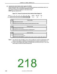
(3) Asynchronous serial interface status register 20 (ASIS20)
ASIS20 indicates the type of a reception error, if it occurs while asynchronous serial interface mode is set.
ASIS20 is set with a 1-bit or 8-bit memory manipulation instruction.
The contents of ASIS20 are undefined in 3-wire serial I/O mode.
RESET input sets ASIS20 to 00H.
Figure 12-5. Format of Asynchronous Serial Interface Status Register 20
Symbol
ASIS20
7
0
6
0
5
0
4
0
3
0
<2> <1> <0>
Address
FF71H
After reset
00H
R/W
R
PE20 FE20 OVE20
PE20
Parity error flag
0
1
No parity error has occurred.
A parity error has occurred (when the parity of transmit data does not match).
FE20
Flaming error flag
No framing error has occurred.
0
1
A framing error has occurred (when stop bit is not detected).Note 1
OVE20
Overrun error flag
No overrun error has occurred.
0
1
An overrun error has occurred.Note 2
(when the next receive operation is completed before the data is read from reception buffer register 20)
Notes 1. Even when the stop bit length is set to 2 bits by setting bit 2 (SL20) of asynchronous serial
interface mode register 20 (ASIM20), the stop bit detection at reception is performed with 1 bit.
2. Be sure to read reception buffer register 20 (RXB20) when an overrun error occurs. If not, every
time the data is received an overrun error will occur.
User’s Manual U15075EJ1V0UM00
218

 NEC [ NEC ]