CHAPTER 12 SERIAL INTERFACE 20
The baud rate transmit/receive clock to be generated is either a signal scaled from the system clock, or a
signal scaled from the clock input to the ASCK20 pin.
(a) Generation of baud rate transmit/receive clock form system clock
The transmit/receive clock is generated by scaling the system clock. The baud rate of a clock
generated from the system clock is estimated by using the following expression.
fX
[Baud rate] =
[Hz]
2
n + 1 × 8
fX: Main system clock oscillation frequency
n: Values in Figure 12-6, determined by the values of TPS200 to TPS203 (2 ≤ n ≤ 8)
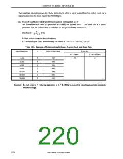
Table 12-3. Example of Relationships Between System Clock and Baud Rate
Baud Rate (bps)
n
BRGC20 Set Value
Error (%)
fX = 5.0 MHz
1.73
fX = 4.9152 MHz
0
1,200
2,400
8
7
6
5
4
3
2
70H
60H
50H
40H
30H
20H
10H
4,800
9,600
19,200
38,400
76,800
Caution Do not select n = 1 during operation at fX = 5.0 MHz because the resulting baud rate exceeds
the rated range.
User’s Manual U15075EJ1V0UM00
220

 NEC [ NEC ]