CHAPTER 12 SERIAL INTERFACE 20
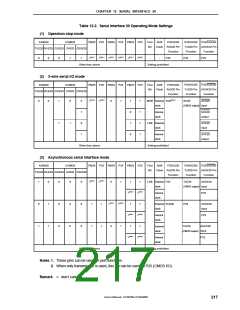
12.3 Serial Interface 20 Control Registers
Serial interface 20 is controlled by the following registers.
• Serial operation mode register 20 (CSIM20)
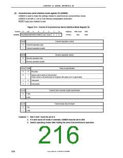
• Asynchronous serial interface mode register 20 (ASIM20)
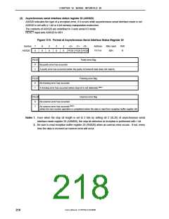
• Asynchronous serial interface status register 20 (ASIS20)
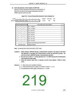
• Baud rate generator control register 20 (BRGC20)
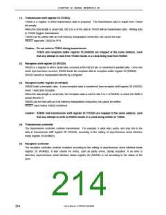
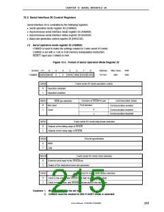
(1) Serial operation mode register 20 (CSIM20)
CSIM20 is used to make the settings related to 3-wire serial I/O mode.
CSIM20 is set with a 1-bit or 8-bit memory manipulation instruction.
RESET input sets CSIM20 to 00H.
Figure 12-3. Format of Serial Operation Mode Register 20
Symbol <7>
6
5
0
4
0
3
2
1
0
Address
FF72H
After reset
00H
R/W
R/W
CSIM20 CSIE20 SSE20
DAP20 DIR20 CSCK20 CKP20
CSIE20
3-wire serial I/O mode operation control
0
1
Operation disabled
Operation enabled
SSE20
Communication status
Function of SS20/P22 pin
Port function
SS20 pin selection
0
1
Not used
Used
Communication enabled
0
1
Communication enabled
Communication disabled
DAP20
3-wire serial I/O mode data phase selection
0
1
Outputs at the falling edge of SCK20
Outputs at the rising edge of SCK20
DIR20
First-bit specification
0
1
MSB
LSB
3-wire serial I/O mode clock selection
External clock input to the SCK20 pin
Output of the dedicated baud rate generator
CSCK20
0
1
CKP20
3-wire serial I/O mode clock phase selection
0
1
Clock is low active, and SCK20 is at high level in the idle state
Clock is high active, and SCK20 is at low level in the idle state
Cautions 1. Bits 4 and 5 must be set to 0.
2. CSIM20 must be cleared to 00H if UART mode is selected.
User’s Manual U15075EJ1V0UM00
215

 NEC [ NEC ]