MUPA64K16 Alto Priority Queue Scheduler
identifier. The UID Manager returns the lowest unused
identifier, and replaces any identifier currently not
used. The basic operations of the UID manager are:
·
STR[4] is one if the most recent UID Get
operation completed and the associated UID Get
Register contains the new UID value.
·
·
UID Get: obtain an unused UID
UID Put: return a UID to the pool of unused UIDs
Register Descriptions
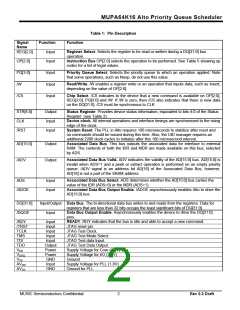
Table 2 gives an overview of the device registers and
their attributes. Figure 3 shows the register datapath.
Pipeline operations are supported; as soon as an
operation begins execution, the input registers are
available to receive data for the next operation.
Input Data Register (1 x 16 bits)
The contents of the Size Register (SR) are cleared
when either the Mode Register (MR) or the Size
Register (SR) detects a WRITE operation. When the
priority queue (PQ) line addresses the SR, the
contents of the SR will be incremented or
decremented by one for INSERT or EXTRACT
operations. The respective Wrap Register (WR) will
be updated via the DQ input port using the PQ line
value and the contents of the Mode Register (MR).
Similarly, the contents of the WR will be cleared when
the MR detects the WRITE operation.
The Input Data Register (IDR) is loaded with an
associated data value for the next INSERT or BOTH
instruction. The IDR is write only. The IDR can be
read via the AD[15:0] bus when ADS is zero.
Input Key Register (1 x 32 bits)
The Input Key Register (IKR) is loaded with an key
value for the next INSERT or BOTH instruction. The
IKR is write only.
Min Data Register (1 x 16 bits)
The Min Data Register (MDR) contains the data
associated with the minimum key of the selected
priority queue. The MDR is loaded by Peek, Extract
and Both instructions. The MDR is read only. The
MDR can be read via the AD[15:0] bus when ADS is
one.
The contents of the Size Registers (SR), Wrap
Registers(WR), Input Key Register (IKR), Input Data
Register(IDR), priority queue, and opcode are stored
in the packet buffer when any of these instructions
(INSERT, EXTRACT, BOTH, PEEK) are detected.
After the completion of the previously issued queue
instruction, these contents are transferred to the
priority queue to execute the priority queue’s next
instruction.
Min Key Register (1 x 32 bits)
The Min Key Register (MKR) contains the minimum
key of the selected priority queue. The MKR is loaded
by the Peek, Extract and Both instructions. The MKR
is read only.
The input buffers are now available to accept
additional queue instructions from the external I/O
interface. Any additional new instructions can be
issued after checking the status information (STR) bits
(either 0 or 1 depending upon the instruction).
Mode Register (1 x 3 bits)
The Mode Register (MR) bits select the number of
priority queues:
·
·
·
·
·
0: one priority queue (64K each)
1: two priority queues (32K each)
2: four priority queues (16K each)
3: eight priority queues (8K each)
4, 5, 6, 7: sixteen priority queues (4K each)
STR[4:0] (Status, Output)
STR[4:0] provide device status information, and is
equivalent to Status Register bits 4:0.
·
STR[0] is one if IKR and IDR are ready to accept
new values; STR[0] is zero if a command has
been issued, but execution has not yet started.
STR[1] is one if MKR and MDR contain new
values to be read; STR[1] is reset to zero if either
the MKR or MDR registers are read.
The MR is read/write and is initialized to all zeros.
Table 3 shows how the MR value affects other
registers in the device.
·
Note: Writing to the mode register will reset all Size
Registers and all Wrap Registers to zero.
·
·
STR[2] is one if the UPR is ready to accept a new
value.
STR[3] is one off any UGR contains a new UID
value to be read.
MUSIC Semiconductors Confidential
4
Rev 0.3 Draft

 MUSIC [ MUSIC SEMICONDUCTORS ]