MUPA64K16 Alto Priority Queue Scheduler
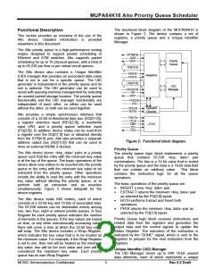
The functional block diagram of the MUPA64K16 is
shown in Figure 2. The device contains a set of
registers, a priority queue and a Unique Identifier
Manager.
Functional Description
This section provides an overview of the use of the
Alto device. Detailed information is provided
elsewhere in this document.
The Alto priority queue is a high-performance sorting
engine designed to support packet scheduling in
Ethernet and ATM switches. Alto supports packet
scheduling for up to 16 physical queues, with a total of
up to 65,536 per flow or per virtual circuit queues.
STR[4:0]
ADS
/ADV
Priority
Queue
AD[15:0]
The Alto device also contains a Unique Identifier
(UID) manager that provides an associated data value
that is not in use for a specific queue. The UID
generator is independent of the priority queue and its
use is optional. The UID generator can be used to
assist with queuing memory management by selecting
an unused packet storage location. The priority queue
functionality and the UID manager functionality are
independent of each other, so either can be used
without the other, or both can be used together.
/ADOE
/DQOE
Registers
DQ[31:0]
UID
Manager
REG[2:0]
/W
RDY
PQ[3:0]
/CS
Operand
Decoder
OP[2:0]
RSTb
Alto provides a simple synchronous interface that
consists of a 32-bit bi-directional data bus (DQ[31:0]),
a register selection input (REG[2:0]), a read/write
input (/W), and a priority queue selection input
(PQ[3:0]). In addition, device status can be read from
a register over the DQ[31:0] bus or obtained directly
from the STR[4:0] pins. Alto also provides a separate
address output bus (AD[15:0]) that can be used to
drive an external SRAM, if desired.
TRSTb
TCLK
TMS
TDI
TDO
JTAG
Figure 2: Functional block diagram.
Priority Queue
The Alto device stores <key, data> pairs in a priority
queue such that the entry with the minimum key value
is at the top of the queue. The basic operations of the
device allow new entries to be inserted into the priority
queue or the entry with the minimum key value to be
extracted from the priority queue. Other operations
include the ability to read the entry with the minimum
key value without altering the priority queue, or to
perform both an extraction and an insertion
simultaneously. Figure 3 shows datapath for the
device registers.
The priority queue logic block implements a priority
queue that contains 65,536 <key, data> pair
combinations. The key is a 32-bit value that is sorted
by the priority queue and the data is a 16-bit data field
that can contain an arbitrary value. This block
contains the instruction logic for all the queue
operations.
The basic operations of the priority queue are:
·
·
INSERT a new <key, data> pair
EXTRACT returns the minimum <key, data> pair
as selected by the PQ[3:0] inputs
BOTH performs Extract and Insert both
operations
The Alto device holds 64K entries, each of which
consists of a 32-bit key and 16 bits of associated data.
The 65,536 entries can be distributed evenly among
one, two, four, eight or sixteen priority queues. A Size
Register for each priority queue indicates the number
of elements in the queues. If the key values are based
on time, or any other monotonically increasing value,
there will come a time at which the 32-bit key value
will wrap. The Alto device includes a Wrap Register,
which indicates the key value that is to be treated as
the minimum value. For example, if the Wrap Register
is set to one, then one will be treated as the minimum
key value, two will be the next value and zero will be
considered the maximum key value. Each priority
queue has its own Wrap Register.
·
·
PEEK returns the minimum <key, data> pair as
selected by the PQ[3:0] inputs
Priority Queue logic block receives instructions and
related data from the registers and generates the
output data and the control signals to update the
Status Register. The execution of the instruction is
indicated by the “DONE” signal, which is sent to the
registers to prepare for the next instruction from the
registers.
Unique Identifier (UID) Manager
The UID Manager stores up to 64K 16-bit unused
data elements, each of which represents a unique
MUSIC Semiconductors Confidential
3
Rev 0.3 Draft

 MUSIC [ MUSIC SEMICONDUCTORS ]